TBEA compensation soft starting device used for large power cage type motor
A high-power, soft-start technology, applied in motor generators/starters, reactive power compensation, reactive power adjustment/elimination/compensation, etc., can solve problems such as impact surge current
- Summary
- Abstract
- Description
- Claims
- Application Information
AI Technical Summary
Problems solved by technology
Method used
Image
Examples
Embodiment 1
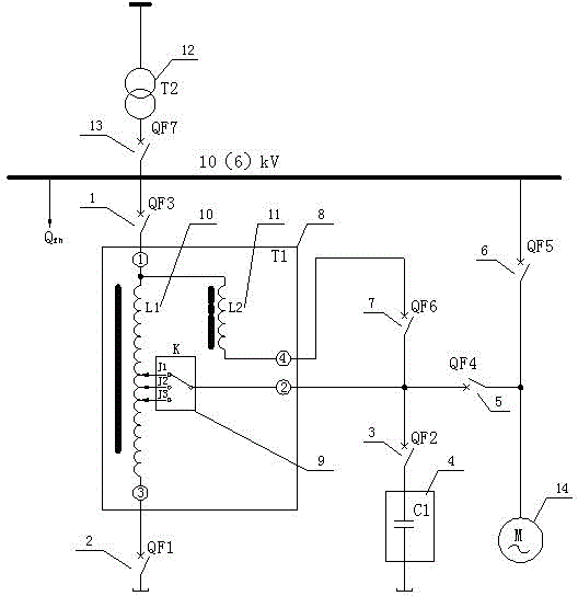
[0019] Example 1 as figure 1shown. The main busbar of the power grid is connected to the input terminal of the incoming line circuit breaker QF7 through the distribution transformer T2, and the outgoing line end of the incoming line circuit breaker QF7 is connected to the 10 (6) kV starting circuit busbar, and then connected to the self-excited starting circuit breaker after the starting circuit busbar is energized The incoming terminal of QF3 of the self-excited starting circuit breaker, and the outgoing terminal of QF3 of the self-excited starting circuit breaker are connected to the external interface ① of the special type self-excited starting transformer T1. The interface ① of the special self-excited starting transformer T1 is internal and connected to two independent internal windings, one of which is connected to the internal independent autotransformer winding L1, and the other is connected to the internal independent reactor characteristic winding L2. The autotransf...
Embodiment 2
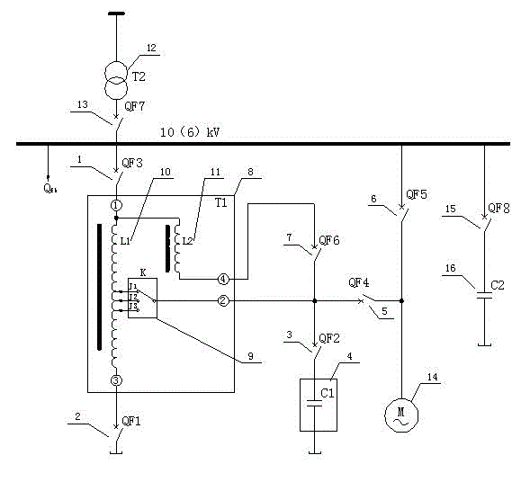
[0024] Example 2 as figure 2 shown. The difference from Embodiment 1 is that an in-situ compensation circuit composed of an in-situ compensation circuit breaker QF8 and an in-situ compensation capacitor C2 connected in series is connected between the external output port ② of the special-type self-excited starting transformer T1 and the star point common terminal.
[0025] The working principle of embodiment 2 of the present invention is:
[0026] The starting circuit of the main circuit step-down current limiting compensation is to connect the main circuit incoming circuit breaker QF7, the main bus of the power grid supplies power to the 10 (6) kV starting circuit bus through the distribution transformer T2 and the incoming circuit breaker QF7, and the series excitation control is connected The circuit breaker QF1 short-circuits the common winding of the special-type starting transformer T1 to form a star point, and then connects the self-excited starting circuit breaker QF...
Embodiment 3
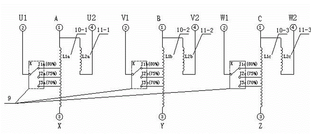
[0030] Example 3 as image 3 , Figure 4 shown. It mainly introduces the internal structure of the special self-excited starting transformer T1. The input part of the winding wiring schematic diagram of the special self-excited starting transformer comes from the three phases A, B and C of the external interface ①, and the winding of the special self-excited starting transformer passes through three The phase-independent autocoupling windings L1a, L1b, L1c are connected to one end of the three-phase external interface ② of the special type self-excited starting transformer through the self-excitation tap of the internal manual tap changer K to select the J1 contact, and the three outputs of the external interface ② are respectively Output U1, V1, W1 three-phase, special-type self-excited starting transformer winding through three-phase independent reactor windings L2a, L2b, L2c through the three outputs of the external interface ④ respectively output U2, V2, W2 three-phase, s...
PUM
 Abstract
Description
Claims
Application Information
 - R&D
- Intellectual Property
- Life Sciences
- Materials
- Tech Scout
- Unparalleled Data Quality
- Higher Quality Content
- 60% Fewer Hallucinations
Browse by: Latest US Patents, China's latest patents, Technical Efficacy Thesaurus, Application Domain, Technology Topic, Popular Technical Reports.
© 2025 PatSnap. All rights reserved.Legal|Privacy policy|Modern Slavery Act Transparency Statement|Sitemap|About US| Contact US: help@patsnap.com


