A new type of knob device

A knob, a new type of technology, is applied in the direction of household heating, lighting and heating equipment, electrical components, etc., which can solve the problems of inconvenient sanitation and cleaning, and achieve the effect of convenient implementation, convenient use, and enhanced experience

Active Publication Date: 2018-01-05
VATTI CORP LTD
View PDF4 Cites 0 Cited by
  • Summary
  • Abstract
  • Description
  • Claims
  • Application Information

AI Technical Summary

Problems solved by technology

[0002] At present, many devices need to indirectly measure the change of the rotation position. For example, when people use a gas stove, they are used to using the rotation method to adjust the firepower. However, the existing plug valve installed on the panel of the electrical equipment is very inconvenient for sanitation and cleaning.

Method used


Image

  • A new type of knob device
  • A new type of knob device

Examples


Embodiment Construction

[0017] The features of the present invention and other related features will be further described in detail below in conjunction with the accompanying drawings through embodiments, so as to facilitate the understanding of those skilled in the art:

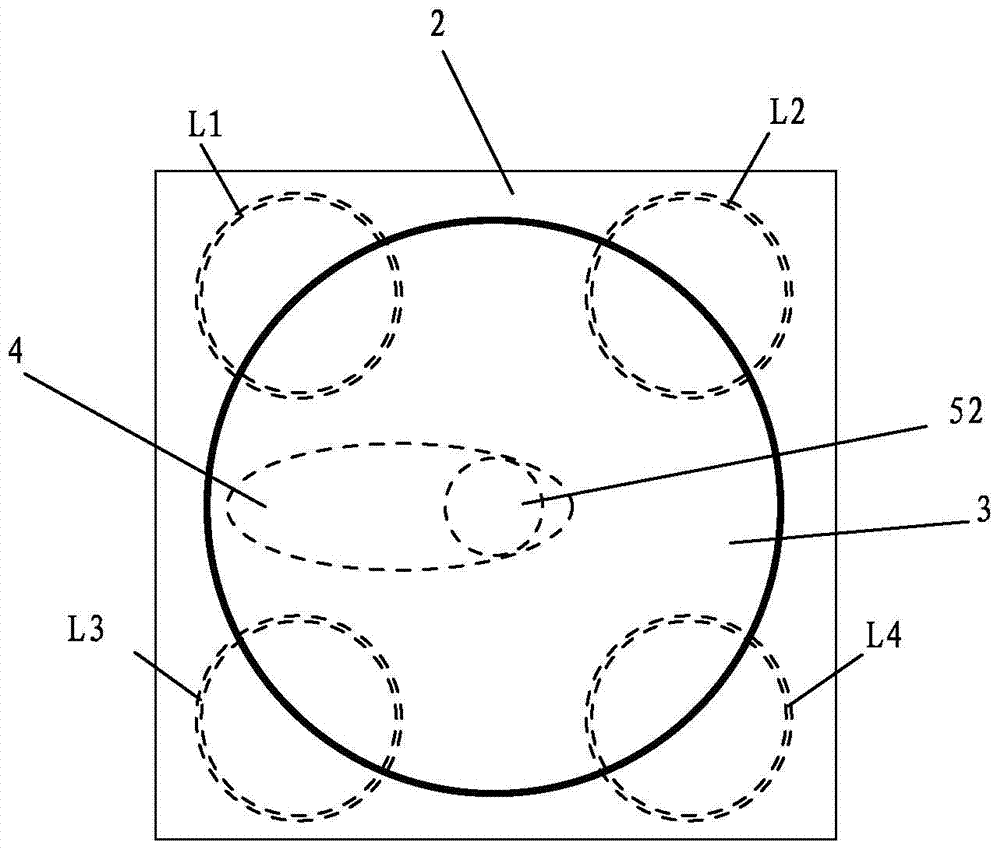
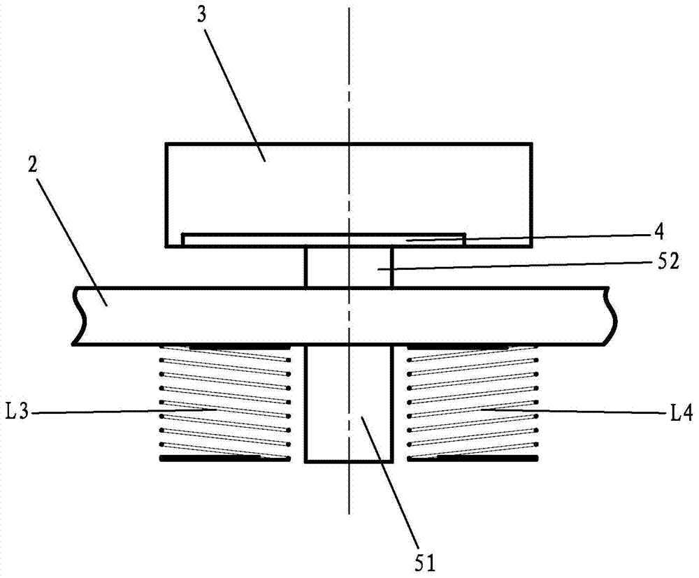
[0018] like figure 1 As shown, a new knob device is characterized in that it includes inductance coils L1, L2, L3, and L4 distributed in a square array for synchronously generating an alternating magnetic field. The finished panel 2, the upper end of the panel 2 is provided with a knob 3, and the knob 3 is provided with an induction plate made of a magnetically permeable material for cutting the magnetic field with the rotation of the knob 3 to change the inductance value of each inductance coil 4. The device also includes a positioning mechanism for positioning the knob 3 on the central axis of the square array so that it can rotate around the central axis of the square array, and a positioning mechanism for controlling the four i...


PUM


Abstract

The invention discloses a novel rotary knob apparatus. The apparatus comprises inductance coils L1, L2, L3 and L4 which are distributed in a square array mode and are used for synchronously generating alternating magnetic fields. An upper end of the square array is provided with a panel made of a non-magnetic-conductive material. An upper end of the panel is provided with a rotary knob. A sensor board which is made of a magnetic conductive material and is used for cutting the magnetic fields along with rotation of the rotary knob so as to change an inductance of each inductance coil is arranged in the rotary knob. The apparatus also comprises a positioning mechanism and a control circuit board, wherein the positioning mechanism is used for positioning the rotary knob on a center axis of the square array so that the positioning mechanism can be conveniently rotated about the center axis of the square array; the control circuit board is used for making the four inductance coils synchronously generate the alternating magnetic fields and detecting the inductance of each inductance coil so as to calculate a rotary knob rotation angle. The structure is simple and the apparatus is easy to realize. When a user cleans the panel, the rotary knob can be removed so that cleaning is convenient.

Description

[technical field] [0001] The invention relates to a novel knob device. [Background technique] [0002] At present, many devices need to indirectly measure the change of the rotation position. For example, when people use gas stoves, they are accustomed to using the rotation method to adjust the firepower. However, the existing stopcocks installed on the panels of electrical equipment are very inconvenient for sanitation and cleaning. [0003] Therefore, it is necessary to solve the above problems. [Content of the invention] [0004] The present invention overcomes the shortcomings of the above-mentioned technologies and provides a novel knob device with a simple structure and easy realization. When the user cleans the panel, the upper knob can be removed, which is convenient for cleaning. [0005] To achieve the above object, the present invention adopts the following technical solutions: [0006] A new type of knob device, including inductance coils L1, L2, L3, L4 distr...

Claims


Application Information

Patent Timeline
Patent Type & Authority Patents(China)
IPC IPC(8): H01H19/14H01H19/11F24C3/12
CPCF24C3/126H01H19/11H01H19/14
Inventor 易洪斌关建国胡正军闫旺潘叶江
Owner VATTI CORP LTD
Why Eureka
Try Eureka