Dielectric filter and manufacturing method thereof

A technology of a dielectric filter and a manufacturing method, which is applied in the field of communication, can solve the problems of affecting the performance parameters of the dielectric filter and increasing the difficulty of processing, etc., and achieve the effects of low processing difficulty, reduced processing difficulty, and high yield rate

Pending Publication Date: 2021-12-21
江苏灿勤科技股份有限公司
View PDF0 Cites 0 Cited by
  • Summary
  • Abstract
  • Description
  • Claims
  • Application Information

AI Technical Summary

Problems solved by technology

[0004] The width of this type of dielectric filter is inversely proportional to the dielectric constant and center frequency of the ceramic material, that is , where C is 300000KM / sec, fo is the center frequency, εr is the dielectric constant, and l is the width of the dielectric filter. According to the formula, when the dielectric constant is fixed, the higher the frequency of the dielectric filter, the corresponding dielectric filter The smaller the width dimension of the dielectric filter is, however, the surface processing circuit and signal electrode of the dielectric filter, as well as opening a resonant hole on the dielectric filter and installing a shielding case, all require the dielectric filter to have a certain width dimension, too small a width dimension It will make the processing more difficult and affect the performance parameters of the dielectric filter. That is, when the width of the dielectric filter is reduced to the limit, the frequency of the dielectric filter is also increased to the limit. Therefore, the existing dielectric filter can only be Achieve a frequency of around 6500MHz

Method used


Image

  • Dielectric filter and manufacturing method thereof
  • Dielectric filter and manufacturing method thereof
  • Dielectric filter and manufacturing method thereof

Examples


Embodiment Construction

[0032] The technical solutions in the embodiments of the present invention will be described in detail below in conjunction with the accompanying drawings in the embodiments of the present invention. Obviously, the described embodiments are only some of the embodiments of the present invention, not all of them. Based on the embodiments of the present invention, all other embodiments obtained by persons of ordinary skill in the art without making creative efforts belong to the protection scope of the present invention.

[0033] In the description of the present invention, the terms "first", "second", and "third" are used for descriptive purposes only, and cannot be understood as indicating or implying relative importance.

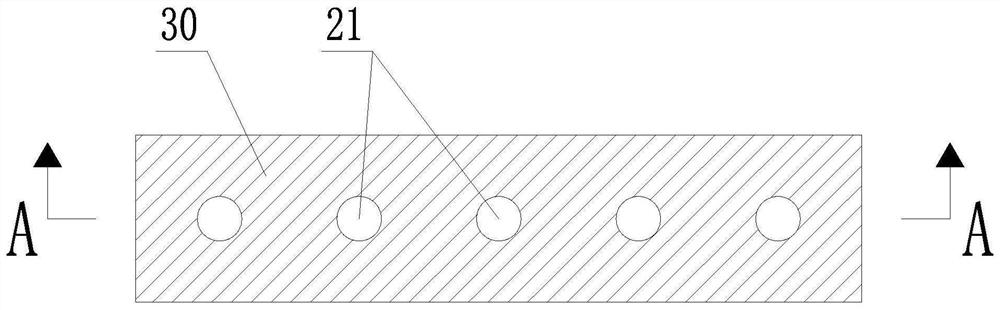
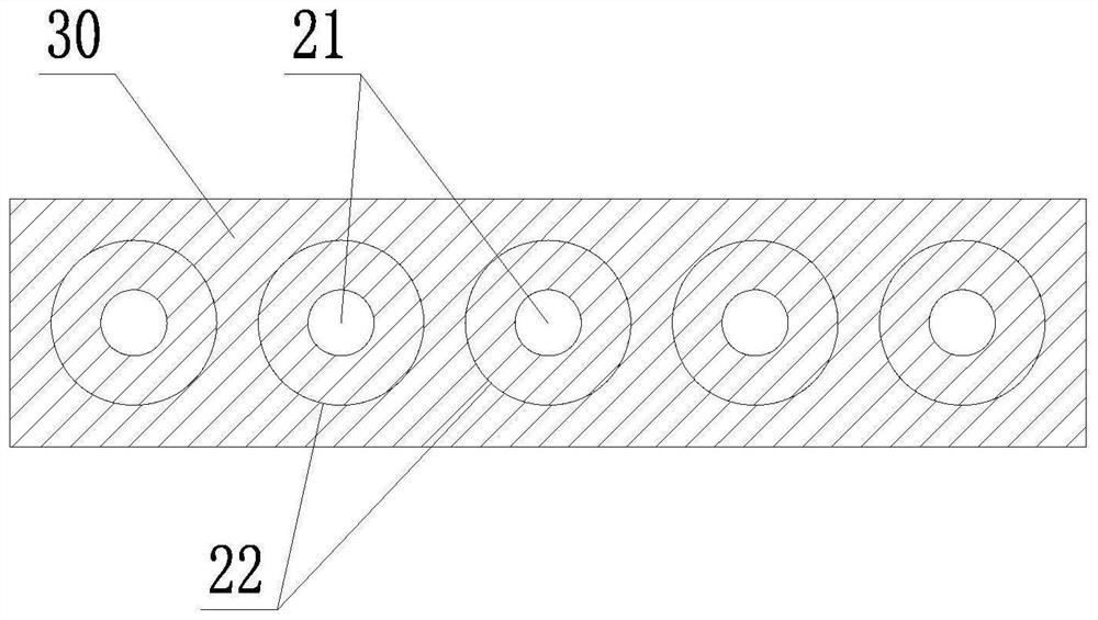
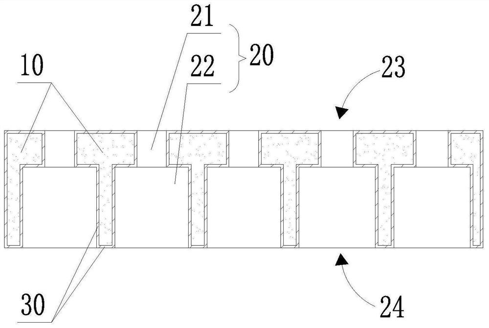
[0034] The up-down and left-right directions described in the present invention are figure 1 In the up and down, left and right directions, the front and rear directions described in the present invention refer to image 3 In the up and down direction, the ...


PUM


Abstract

A dielectric filter provided by the invention comprises a filter body, a resonance hole penetrating through the filter body in the front-back direction, and conductive layers covering the inner wall surface of the resonance hole and the surface of the filter body, wherein the conductive layers on the front and back surfaces of the filter body respectively form a circuit and a signal electrode. The resonance hole comprises a first straight hole and a second straight hole which are communicated, the hole diameter and the hole depth of the second straight hole are larger than those of the first straight hole, the width size of the dielectric filter does not need to be reduced, the frequency of the dielectric filter can be increased by changing an inductance value of an equivalent circuit of the dielectric filter, the frequency of the dielectric filter is higher under the condition of the same size, and the hole diameter of the second straight hole is increased, so that the processing difficulty is reduced, and the performance parameters of the dielectric filter are better. The manufacturing method of the dielectric filter is easy in operation, low in machining difficulty, high in yield and suitable for batch production, extra cost is not generated, and the manufactured dielectric filter is high in frequency and good in performance parameter.

Description

technical field [0001] The present application relates to the technical field of communications, and in particular to a dielectric filter and a method for manufacturing the dielectric filter. Background technique [0002] Dielectric filter (English Dielectric filter) is designed and manufactured by using the characteristics of low loss, high dielectric constant, frequency temperature coefficient and thermal expansion coefficient of dielectric ceramic materials, and can withstand high power. Ladder lines connected in series or parallel. [0003] There are two ways to realize the general structure of conventional dielectric filters. One structure is to set N (N ≥ 2) resonant cavities on an independent ceramic from the top to the bottom. This structure is commonly known as a one-piece dielectric filter; Another structure is to open a resonant cavity penetrating from the top to the bottom on the independent ceramic to form a single resonator, and N (N≥2) single resonators are a...

Claims


Application Information

Patent Timeline
Patent Type & Authority Applications(China)
IPC IPC(8): H01P1/20H01P11/00
CPCH01P1/2002H01P11/007
Inventor 朱琦倪玉荣何胜
Owner 江苏灿勤科技股份有限公司
Why Eureka
Try Eureka