Drill head for a deep hole drilling tool for BTA deep hole drilling, and deep hole drilling tool

A technology for deep hole drilling and drill bits, which is applied in the direction of drilling/drilling equipment, drilling tool accessories, manufacturing tools, etc. It can solve the problems of drilling quality impact, frequent tool replacement, no tool life, etc., and achieve the trend of vibration Minimum, increased tool life, and improved drilling quality

Inactive Publication Date: 2013-03-20
TBT TIEFBOHRTECHN
View PDF8 Cites 16 Cited by
  • Summary
  • Abstract
  • Description
  • Claims
  • Application Information

AI Technical Summary

Problems solved by technology

However, it is clear that the known BTA deep hole drilling tools or the drill heads of these BTA deep hole drilling tools do not have a sufficient tool life and / or do not achieve sufficient drilling during machining of some materials compared to other materials quality
In particular, the rounded chamfer on the secondary cutting edge, which forms a three-point bearing contact with the two guide pads, is heavily loaded during BTA deep hole drilling in these materials, and therefore the cutting edge must be are replaced, which adversely affects the cost of
Short tool life means frequent tool changes and thus increased tool investment and lost productivity
It has also been shown that, in the machining of some materials, the known BTA deep hole drilling tools tend to vibrate during the deep hole drilling operation, which likewise has an adverse effect on the drilling quality

Method used


Image

  • Drill head for a deep hole drilling tool for BTA deep hole drilling, and deep hole drilling tool
  • Drill head for a deep hole drilling tool for BTA deep hole drilling, and deep hole drilling tool
  • Drill head for a deep hole drilling tool for BTA deep hole drilling, and deep hole drilling tool

Examples


Embodiment Construction

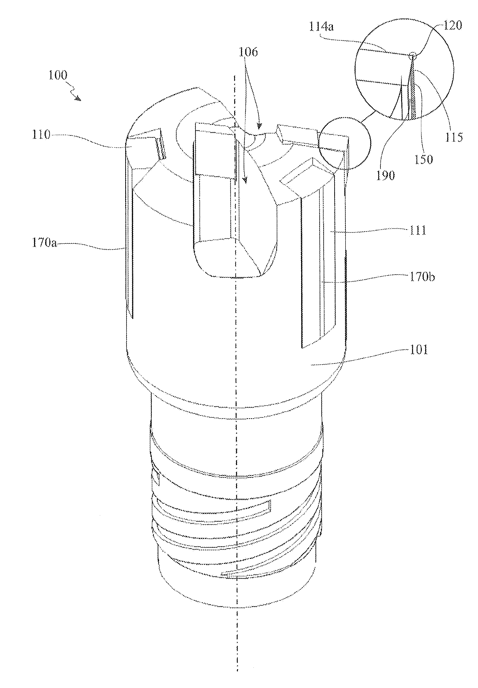
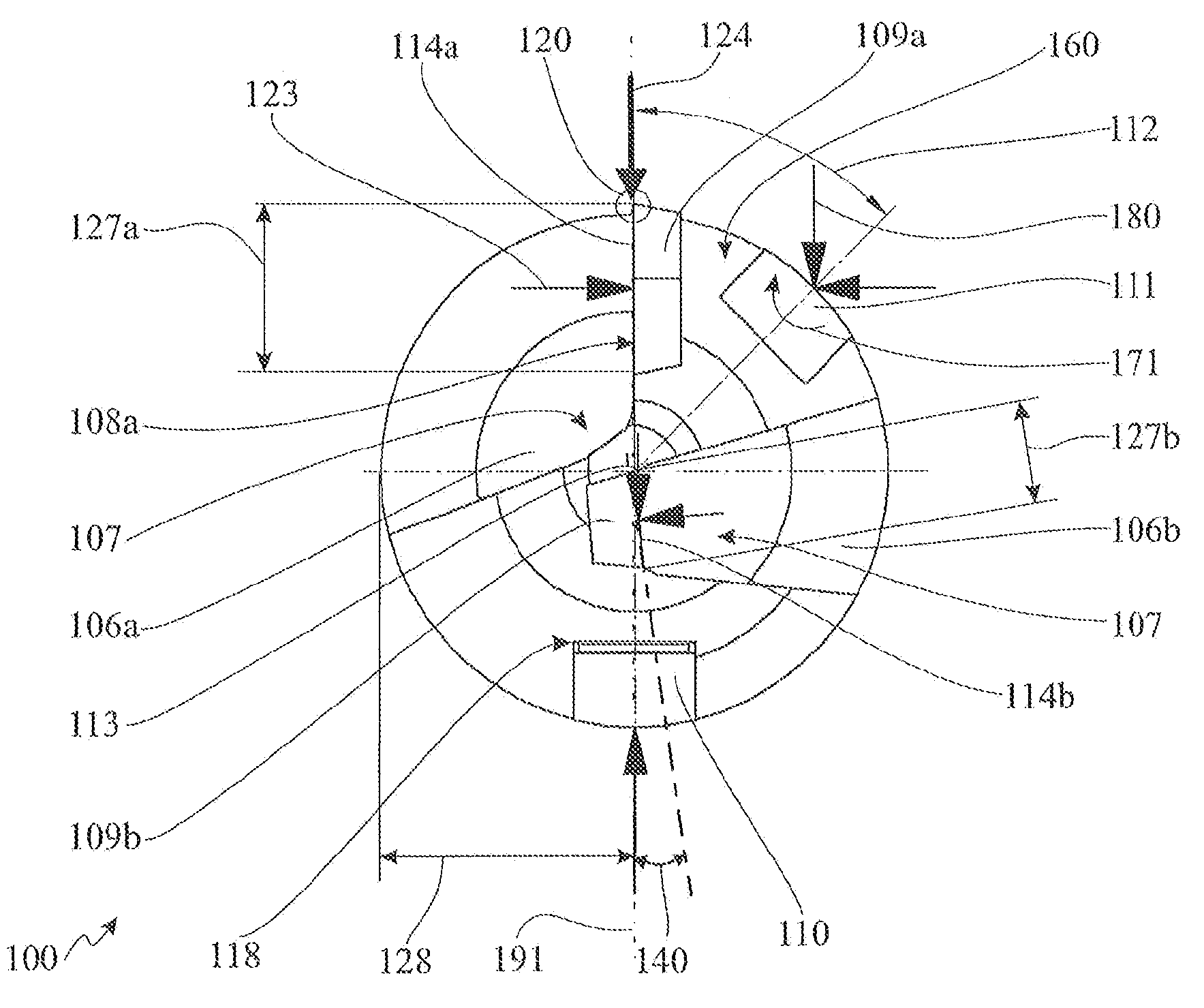
[0045] figure 1 An exemplary embodiment of a drill 100 with a cutting edge 109 which is divided into two partial cutting edges 109a and 109b is shown in perspective. The drill bit 100 shown has a substantially cylindrical drill body 101 , which is rotatable about an axis of rotation 113 and has a drilling region 102 , and a shank region 103 . The shank region 103 is designed to be connected to a drill pipe not shown here. For the exemplary embodiment shown, special connecting threads 104 are provided to connect the drill bit 100 to the drill pipe. It may be a conventional single start or four thread connecting thread for BTA drill bits. In the case of very small drilling diameters in the range of approximately 7 mm to 12 mm, the drill bit can even be incorporated directly into the drill pipe. For large deep hole drilling tools, the bit can also be flanged.

[0046] The cutting edge 109 is arranged on the drilling side 160 of the drill body 101 , wherein the two partial cut...


PUM

PropertyMeasurementUnit
angleaaaaaaaaaa

Abstract

A drill head (100) for a BTA / STS or ejector deep hole drilling tool, comprising a drill head body (101) that can be rotated about an axis of rotation (113), having a drilling side (160) and a hollow channel (107) with a chip collecting opening (106) on the drilling side (160), a cutting blade (109) located thereon, which has a main cutting blade edge (114) and a secondary cutting blade edge (115), wherein the secondary cutting blade is arranged on a radial outer side of the cutting blade and the main cutting blade edge (114) and the secondary cutting blade edge (115) form a cutting blade corner (120) and define a face (108), which is arranged adjacent to the chip collecting opening (106), and bearing pads (110, 111), wherein a first bearing pad (111) is arranged in the circumferential half of the drill head body (101) that is averted away from the face (108); and a second bearing pad (110) is arranged diametrically opposite the cutting blade corner (120). At the same time, it is provided that the first bearing pad (111) is arranged offset from the cutting blade corner (120) by a bearing pad angle (112), measured in the circumferential direction of the drill head (100). According to the invention, the bearing pad angle (112) is less than 70 degrees.

Description

technical field [0001] The invention relates to a drill bit for a deep hole drilling tool for BTA / STS or ejector deep hole drilling according to the preamble of claim 1 and a deep hole drilling tool according to the preamble of claim 12 . Background technique [0002] Deep hole drilling is a special drilling method, especially used to produce boreholes with a diameter of 1mm to 1500mm and a depth greater than three times the diameter, while even very deep holes with a depth / diameter ratio greater than 200 can be produced. drilling. Deep hole drilling tools usually consist of a drill shank, also called drill tube in the case of deep hole drilling tools and used as an extension, and attached to the front end of the drill shank, on which one or more cutting edge. [0003] Deep hole drilling is characterized by a continuous supply of cooling lubricant under pressure and continuous chip removal without chip removal strokes. This means that even deep boreholes can be produced i...

Claims


Application Information

Patent Timeline
Patent Type & Authority Applications(China)
IPC IPC(8): B23B51/04
CPCB23B2260/004B23B2251/422B23B51/0493B23B51/0054B23B51/06B23B2251/56Y10T408/45B23B51/063B23B51/04B23B51/02
Inventor H.兰德克A.贝恩特
Owner TBT TIEFBOHRTECHN
Why Eureka
Try Eureka