Ceramic metal halide lamp
A halide lamp and ceramic metal technology, which is applied to the parts of gas discharge lamps, discharge lamps with multiple main discharge paths, etc., can solve the problems of undocumented ceramic metal halide lamps, achieve uniform light distribution, and reduce radiation exposure. average effect
- Summary
- Abstract
- Description
- Claims
- Application Information
AI Technical Summary
Problems solved by technology
Method used
Image
Examples
no. 1 Embodiment approach
[0043] (structure)
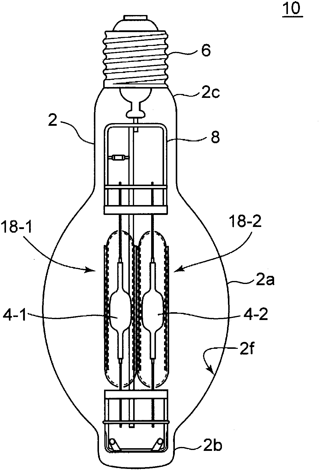
[0044] figure 1 It is a figure explaining the structure of the ceramic metal halide lamp which has two arc tubes of 1st Embodiment. As shown in the figure, the lamp 10 has two luminous tubes 4-1, 4-2 sealed inside the outer bulb 2, and the luminous tubes are respectively surrounded and protected by inner tubes 18-1, 18-2. On one end of the outer bulb 2 is engaged a lamp cap 6 . The light-emitting tube 4 is supported at a predetermined position by the mounting portion 8 on which the inner tube 18 is mounted, and power is supplied. The luminous tube 4 is made of translucent ceramics, and the inner tube 18 is made of transparent quartz glass.
[0045] The outer ball 2 is made of translucent hard glass such as borosilicate glass, for example. The outer bulb 2 has a BT shape, and the BT shape has a central portion 2a with the largest diameter, a top portion 2b on the lower side as viewed in the figure, and a neck portion 2c connected to the upper lamp cap. ...
no. 2 Embodiment approach
[0069] In the first embodiment, the linear transmittance SR is made the same throughout the lamp bulb 2 . However, the linear transmittance SR may also be changed according to the position of the lamp outer sphere. The second embodiment is an embodiment in which the linear transmittance SR is changed according to the position in the height direction (axis direction) of the lamp bulb.
[0070] Figure 13 The lamp 10-1 of the second embodiment is shown, and here, the outer bulb is divided into three regions from the top 2b to the neck 2c into a region B, a region A, and a region B. This lamp 10 - 1 is a lamp in which the linear transmittance SR is relatively high in the region B and the linear transmittance SR is relatively low in the region A. Shading is especially problematic in area A. Therefore, by relatively reducing the in-line transmittance SR of the region A, the problem of light shielding can be further reduced. By relatively low raising the in-line transmittance SR...
no. 3 Embodiment approach
[0072] The third embodiment is an embodiment in which the linear transmittance SR is changed according to the position in the circumferential direction of the lamp outer bulb 2 (the outer spherical circumferential direction of the section perpendicular to the axis).
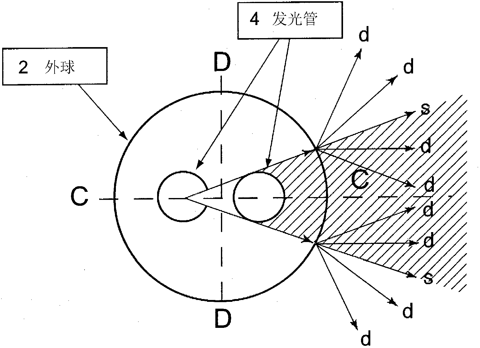
[0073] Figure 14 The lamp 10 - 2 according to the third embodiment is shown, and is a schematic diagram of a cross section in a direction perpendicular to the axis of the lamp outer bulb 2 . The arrangement direction of the two luminous tubes 4 was defined as a region C, and the facing direction was defined as a region D, and four divisions were performed. This lamp 10 - 2 is a lamp in which the in-line transmittance SR is relatively increased in the region C of the outer sphere 2 and the in-line transmittance SR is relatively reduced in the region D of the outer sphere 2 . By relatively reducing the in-line transmittance SR of the region D, the diffusivity of the light irradiated to the region D can be improve...
PUM
 Abstract
Description
Claims
Application Information
 - R&D
- Intellectual Property
- Life Sciences
- Materials
- Tech Scout
- Unparalleled Data Quality
- Higher Quality Content
- 60% Fewer Hallucinations
Browse by: Latest US Patents, China's latest patents, Technical Efficacy Thesaurus, Application Domain, Technology Topic, Popular Technical Reports.
© 2025 PatSnap. All rights reserved.Legal|Privacy policy|Modern Slavery Act Transparency Statement|Sitemap|About US| Contact US: help@patsnap.com


