Ceramic metal halide lamp

A technology of halide lamps and ceramic metals, which is applied to parts of gas discharge lamps, discharge lamps with multiple main discharge paths, etc., can solve the problems of ceramic metal halide lamps that have not been recorded, achieve uniform light distribution, and reduce uneven irradiation average effect

Inactive Publication Date: 2013-09-25
IWASAKI ELECTRIC CO LTD
View PDF5 Cites 0 Cited by
  • Summary
  • Abstract
  • Description
  • Claims
  • Application Information

AI Technical Summary

Problems solved by technology

However, the object of Patent Document 1 is a bulb-type fluorescent lamp in which an outer tube bulb covers a helically bent arc tube (lines 14-15 on page 2), and there is no description of what is the object of the invention of the present application. Contents related to ceramic metal halide lamp equipped with 2 luminous tubes that light up easily with one lamp
[0012] Likewise, neither Patent Document 2 nor Patent Document 3 discloses anything related to a ceramic metal halide lamp provided with two luminescent tubes, which is the object of the invention of the present application and always lights only one lamp that is easy to light.

Method used


Image

  • Ceramic metal halide lamp
  • Ceramic metal halide lamp
  • Ceramic metal halide lamp

Examples


no. 1 Embodiment approach

[0043] (structure)

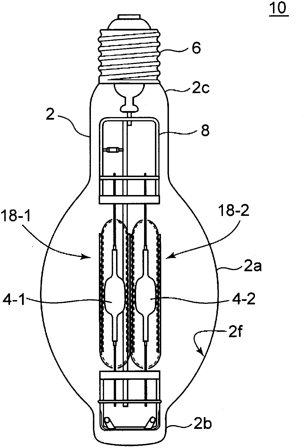
[0044] figure 1 It is a figure explaining the structure of the ceramic metal halide lamp which has two arc tubes of 1st Embodiment. As shown in the figure, the lamp 10 has two luminous tubes 4-1, 4-2 sealed inside the outer bulb 2, and the luminous tubes are respectively surrounded and protected by inner tubes 18-1, 18-2. On one end of the outer bulb 2 is engaged a lamp cap 6 . The light-emitting tube 4 is supported at a predetermined position by the mounting portion 8 on which the inner tube 18 is mounted, and power is supplied. The luminous tube 4 is made of translucent ceramics, and the inner tube 18 is made of transparent quartz glass.

[0045] The outer ball 2 is made of translucent hard glass such as borosilicate glass, for example. The outer bulb 2 has a BT shape, and the BT shape has a central portion 2a with the largest diameter, a top portion 2b on the lower side as viewed in the figure, and a neck portion 2c connected to the upper lamp cap. ...

no. 2 Embodiment approach

[0069] In the first embodiment, the linear transmittance SR is made the same throughout the lamp bulb 2 . However, the linear transmittance SR may also be changed according to the position of the lamp outer sphere. The second embodiment is an embodiment in which the linear transmittance SR is changed according to the position in the height direction (axis direction) of the lamp bulb.

[0070] Figure 13 The lamp 10-1 of the second embodiment is shown, and here, the outer bulb is divided into three regions from the top 2b to the neck 2c into a region B, a region A, and a region B. This lamp 10 - 1 is a lamp in which the linear transmittance SR is relatively high in the region B and the linear transmittance SR is relatively low in the region A. Shading is especially problematic in area A. Therefore, by relatively reducing the in-line transmittance SR of the region A, the problem of light shielding can be further reduced. By relatively low raising the in-line transmittance SR...

no. 3 Embodiment approach

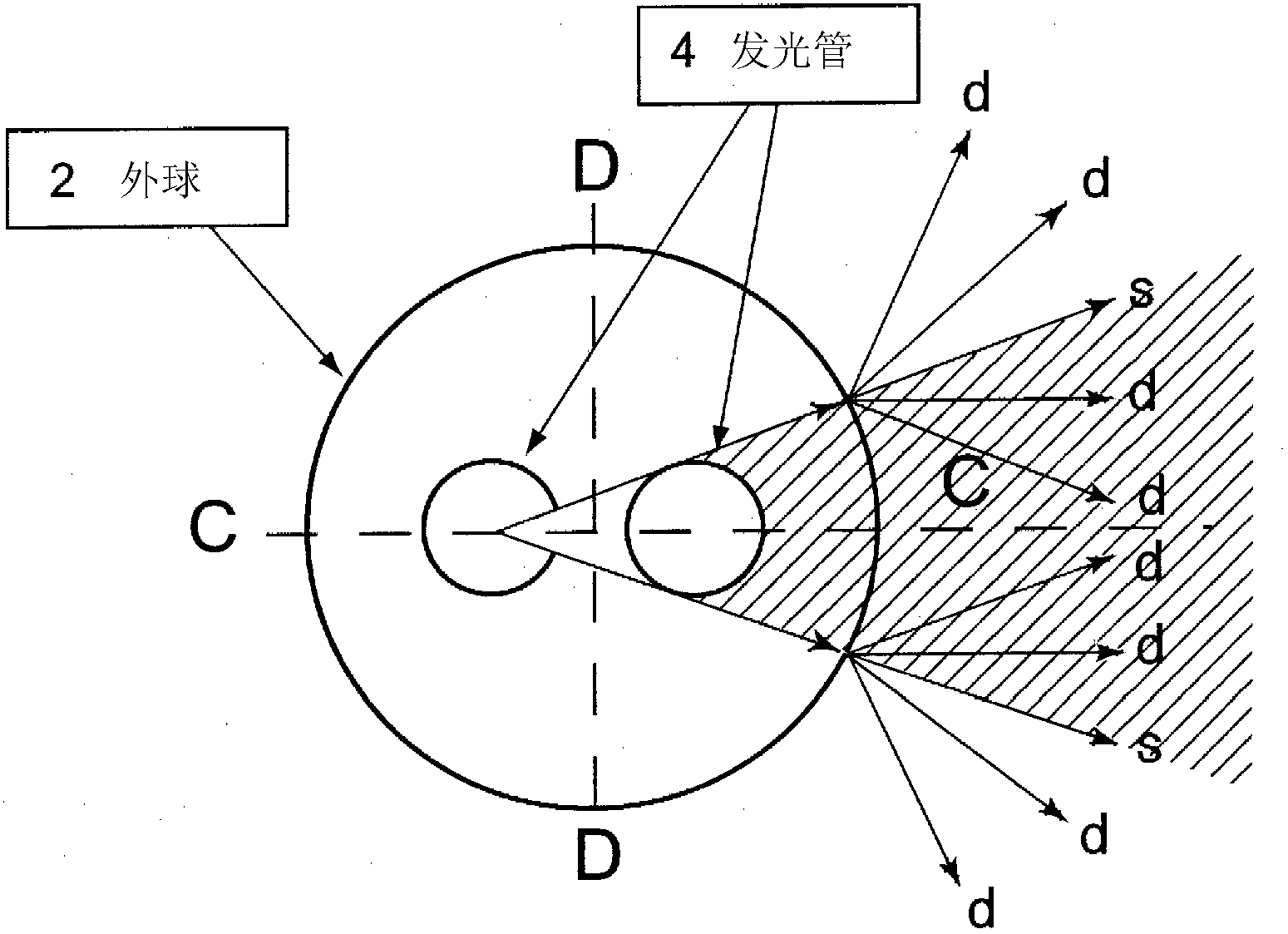
[0072] The third embodiment is an embodiment in which the linear transmittance SR is changed according to the position in the circumferential direction of the lamp outer bulb 2 (the outer spherical circumferential direction of the section perpendicular to the axis).

[0073] Figure 14 The lamp 10 - 2 according to the third embodiment is shown, and is a schematic diagram of a cross section in a direction perpendicular to the axis of the lamp outer bulb 2 . The arrangement direction of the two luminous tubes 4 was defined as a region C, and the facing direction was defined as a region D, and four divisions were performed. This lamp 10 - 2 is a lamp in which the in-line transmittance SR is relatively increased in the region C of the outer sphere 2 and the in-line transmittance SR is relatively reduced in the region D of the outer sphere 2 . By relatively reducing the in-line transmittance SR of the region D, the diffusibility of light irradiated to the region D can be improved,...


PUM


Abstract

Provided is a ceramic metal halide lamp (10) configured so that a single readily lightable tube is lit from among two luminescent tubes (4-1, 4-2), wherein unevenness of radiation is reduced and a uniform light distribution is achieved. The ceramic metal halide lamp (10) comprises: two luminescent tubes (4-1, 4-2), of which only a single readily lightable tube is always lit; and an outer bulb (2) for sealing in the two luminescent tubes. A diffusion film (2f) is formed on the outer bulb, light rays from the single luminescent tube in the lit state are partially diffused by the diffusion film, and the in-line transmittance (SR) of the diffusion film is 5% < SR < 50%.

Description

technical field [0001] This invention relates to ceramic metal halide lamps. More specifically, it relates to a diffusion film on the outer spherical surface of a ceramic metal halide lamp having two arc tubes and always lighting only one of them which is easy to light. Background technique [0002] High-intensity discharge lamps (HID lamps) such as high-pressure mercury lamps, high-pressure sodium lamps, metal halide lamps, and ceramic metal halide lamps emit light using discharge between electrodes. Therefore, compared with an incandescent light bulb, it has various features such as a large light beam, suitable for lighting a large-scale space, and good energy efficiency. Therefore, it is widely used as lighting for roads, shops, factories, etc., location lighting for TV and movies, and headlights for automobiles and railway vehicles. [0003] Among HID lamps, metal halide lamps that use metal halides as luminescent substances have advantages such as excellent color rend...

Claims


Application Information

Patent Timeline
Patent Type & Authority Patents(China)
IPC IPC(8): H01J61/34H01J61/92
CPCH01J61/34H01J61/92H01J61/35
Inventor 大河原亮前原昭美松本泰久西村纯平
Owner IWASAKI ELECTRIC CO LTD
Why Eureka
Try Eureka