Laser annealing apparatus

a laser annealing and annealing technology, applied in the direction of laser beam welding apparatus, manufacturing tools, welding/soldering/cutting articles, etc., can solve the problems of process instability, adverse effect on device characteristics, and oxidation of silicon, so as to reduce the unevenness of irradiation and reduce the unevenness of laser ligh

Active Publication Date: 2013-11-05
IHI CORP
View PDF60 Cites 4 Cited by
  • Summary
  • Abstract
  • Description
  • Claims
  • Application Information

AI Technical Summary

Benefits of technology

[0015]The present invention has been made in consideration of the above-mentioned problems, and an object of the present invention is to provide a laser annealing apparatus capable of reducing irradiation unevenness of laser light caused by a refraction phenomenon of laser light due to fluctuation (variation) in the temperature of inert gas.

Problems solved by technology

However, the low-temperature polysilicon has a problem in that if oxygen is included in the annealing atmosphere, the silicon is oxidized during heating to have an adverse effect on the device characteristics.
When the laser annealing using the supply of nitrogen as described above is performed, due to a difference in the flow rate of the nitrogen gas and variation in the ambient air temperature resulting from the change of seasons or the like, a problem that the process becomes unstable occurs, such as the occurrence of irradiation unevenness.

Method used


Image

  • Laser annealing apparatus
  • Laser annealing apparatus
  • Laser annealing apparatus

Examples


Embodiment Construction

[0030]Preferred embodiments of the present invention will be described below in detail with reference to the accompanying drawings. The same reference numerals are given to common portions in each of the drawings to avoid redundant description.

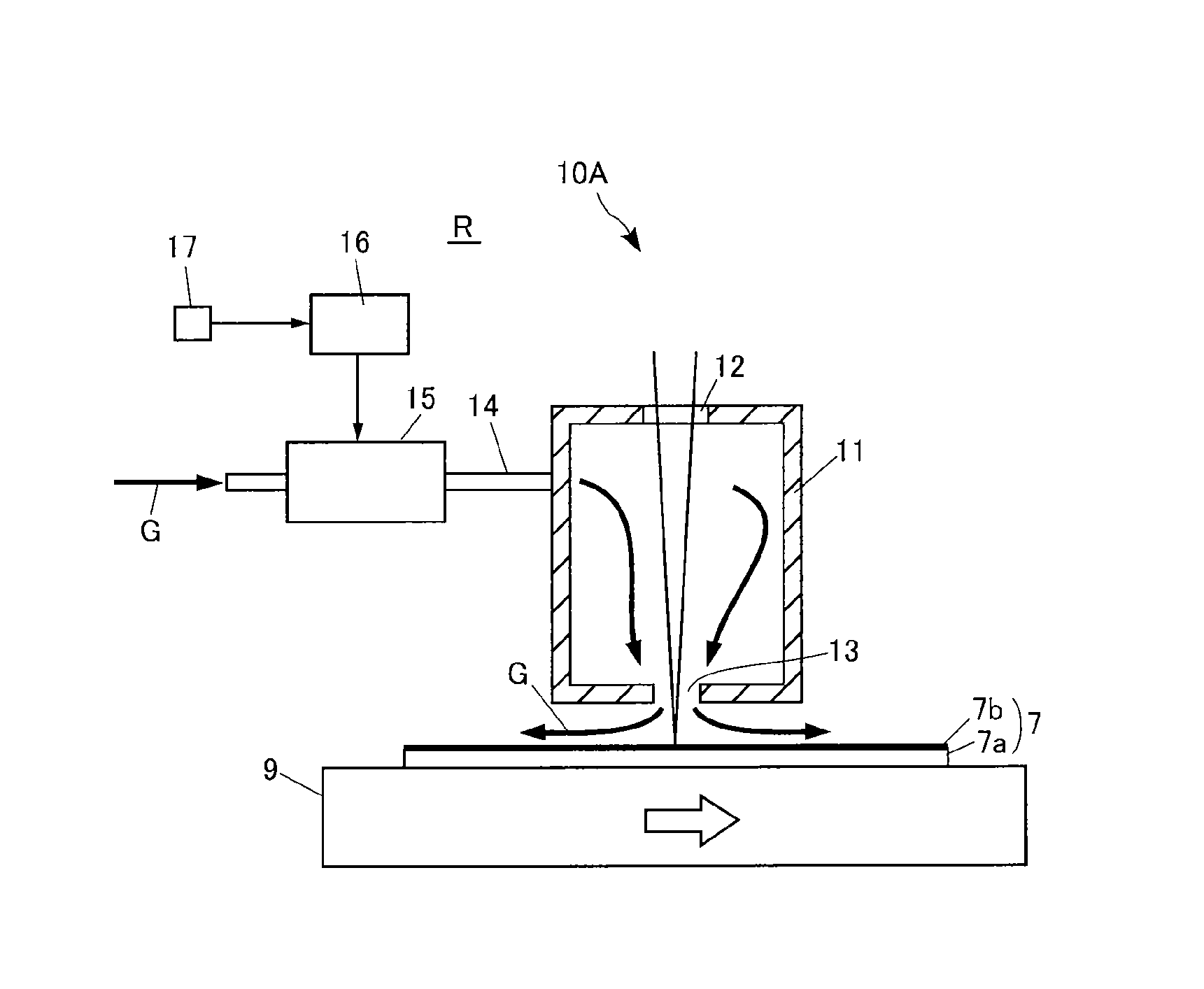
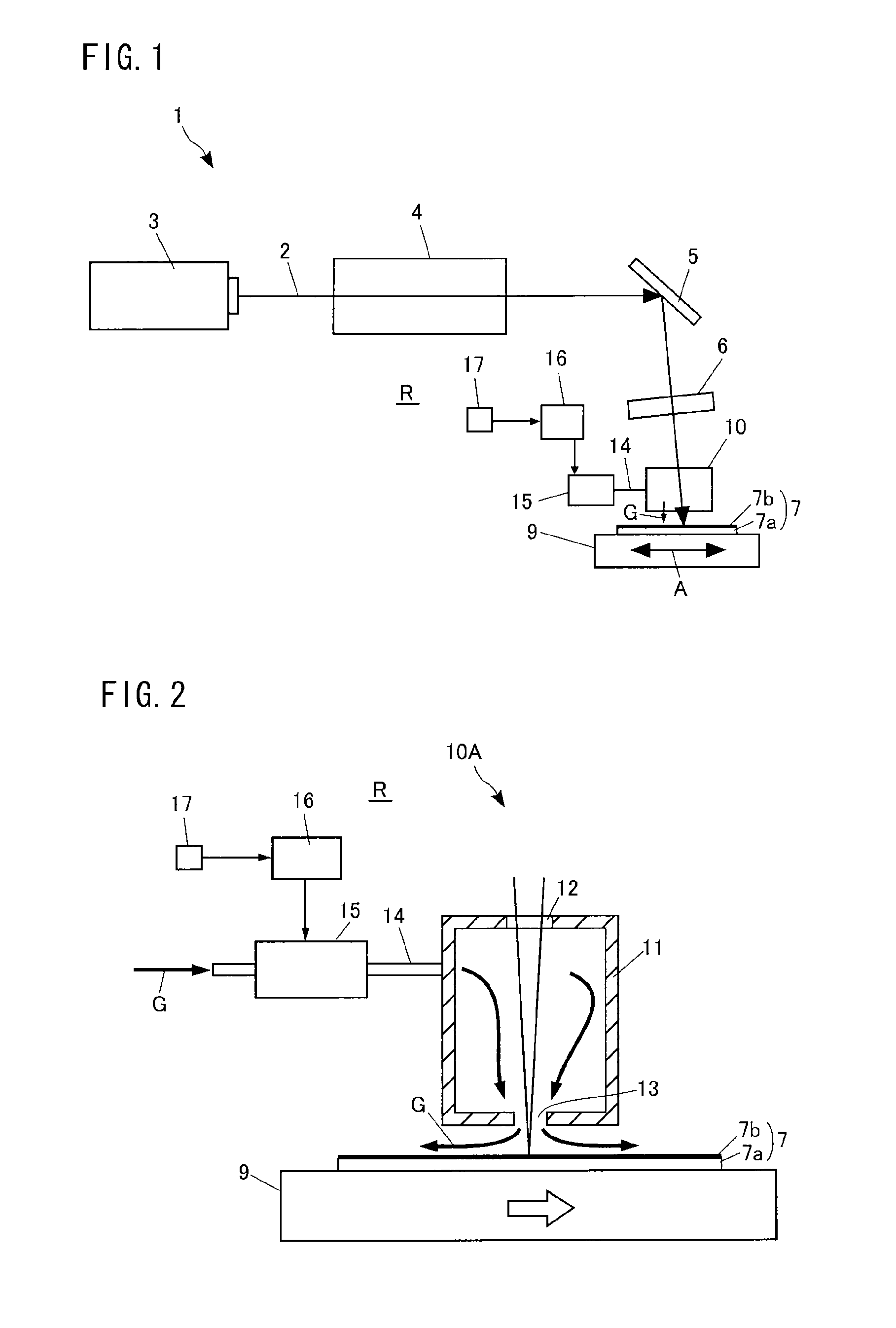
[0031]FIG. 1 is a diagram illustrating an entire configuration of a laser annealing apparatus 1 according to an embodiment of the present invention. The laser annealing apparatus 1 includes, as its basic constituent elements, a laser light source 3 that emits laser light 2, a beam shaping optical system 4 that shapes the laser light 2 from the laser light source 3 into a desired beam shape, a reflecting mirror 5 that reflects the laser light 2 towards a workpiece to be processed 7, a condensing lens 6 that condenses the laser light 2 from the reflecting mirror 5 onto the surface of the workpiece 7, and a movable stage 9 that moves in a direction (direction indicated by arrow A in the figure) crossing the laser light 2 while carrying the workpi...


PUM

PropertyMeasurementUnit
distanceaaaaaaaaaa
temperatureaaaaaaaaaa
gas temperatureaaaaaaaaaa

Abstract

A laser annealing apparatus is provided that is capable of reducing irradiation unevenness of laser light caused by a refraction phenomenon of the laser light due to fluctuation in the temperature of inert gas. The laser annealing apparatus includes a gas supply unit for supplying inert gas G to at least a laser irradiation area of a workpiece, and a gas temperature controller for regulating the temperature of the inert gas G. The gas temperature controller controls the temperature of the inert gas G supplied to the laser irradiation area so as to decrease a temperature difference between the temperature of the inert gas G and the atmospheric temperature of a space (a room R) that is disposed outside the supply area of the inert gas so the temperature controlled inert gas surrounds the optical path of the laser light.

Description

[0001]This is a National Phase Application in the United States of International Patent Application No. PCT / JP2009 / 061016 filed Jun. 17, 2009, which claims priority on Japanese Patent Application No. 2008-170007, filed Jun. 30, 2008. The entire disclosures of the above patent applications are hereby incorporated by reference.BACKGROUND OF THE INVENTION[0002]1. Technical Field of the Invention[0003]The present invention relates to a laser annealing apparatus for performing an annealing treatment on a workpiece to be processed by irradiating the workpiece with laser light.[0004]2. Description of the Related Art[0005]In recent years, a thin film transistor (TFT) in which a polysilicon film is used for a channel layer has been widely used as a switching element of a semiconductor device and a liquid crystal display. The polysilicon film used for the channel layer of the thin film transistor is generally manufactured using a process called a low-temperature polysilicon. The low-temperatu...

Claims


Application Information

Patent Timeline
Patent Type & Authority Patents(United States)
IPC IPC(8): B23K26/00B23K26/02H01L21/268H01L21/20
CPCB23K26/147B23K26/365B23K26/409B23K26/422H01L21/268H01L21/02532H01L21/02675H01L21/67115B23K26/702B23K26/0853B23K26/127B23K26/128B23K2103/56
Inventor KAWAGUCHI, NORIHITOKAWAKAMI, RYUSUKENISHIDA, KENICHIROIZAWA, JUNMASAKI, MIYUKIMORITA, MASARU
Owner IHI CORP
Why Eureka
Try Eureka