Laser Annealing Apparatus and Method

a technology of laser annealing and annealing equipment, which is applied in the field methods, can solve the problems of unpractical drift correction device b>41/b> disclosed in patent document 2 and the rise of production cost and size of laser annealing equipment, and achieve the effect of reducing irradiation unevenness

Active Publication Date: 2009-09-03
SEMICON ENERGY LAB CO LTD
View PDF4 Cites 29 Cited by
  • Summary
  • Abstract
  • Description
  • Claims
  • Application Information

AI Technical Summary

Benefits of technology

[0021]In accordance with the present invention, it is possible to reduce irradiation unevenness caused by the drift occurring in the short-axis direction of the beam, without adding a new beam shaping unit and affecting the propagation characteristic of the beam in the optical resonator.

Problems solved by technology

Therefore, drastic rise in production cost and increase in size of the laser annealing apparatus are inevitable.
Therefore, the drift correction device 41 disclosed in Patent Document 2 is not practical.

Method used


Image

  • Laser Annealing Apparatus and Method
  • Laser Annealing Apparatus and Method
  • Laser Annealing Apparatus and Method

Examples


Embodiment Construction

[0029]An embodiment mode of the present invention will be described below in detail with reference to the accompanying drawings. Note that portions common in the drawings are denoted with the same reference numeral and description to such portions is not repeated.

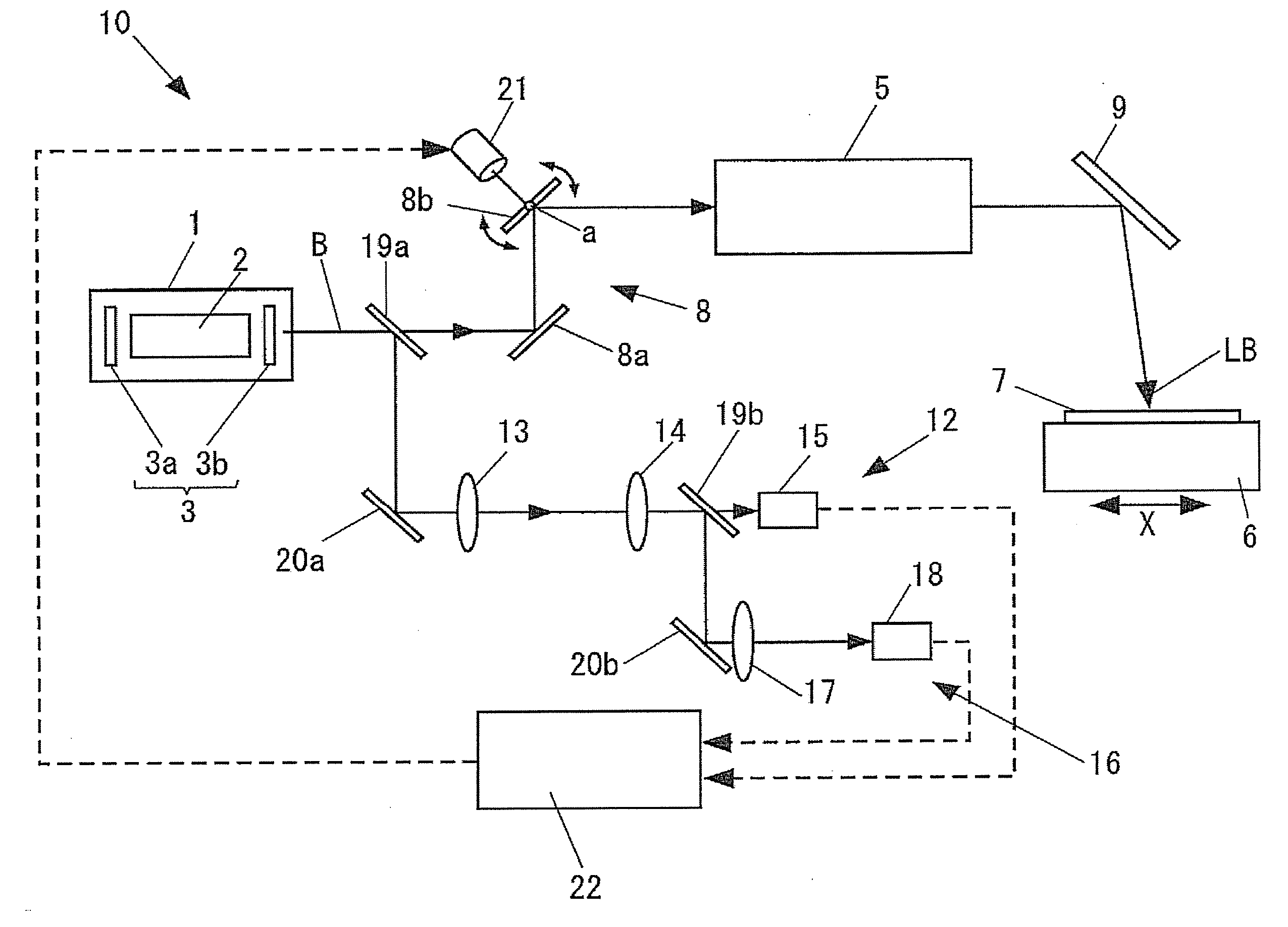
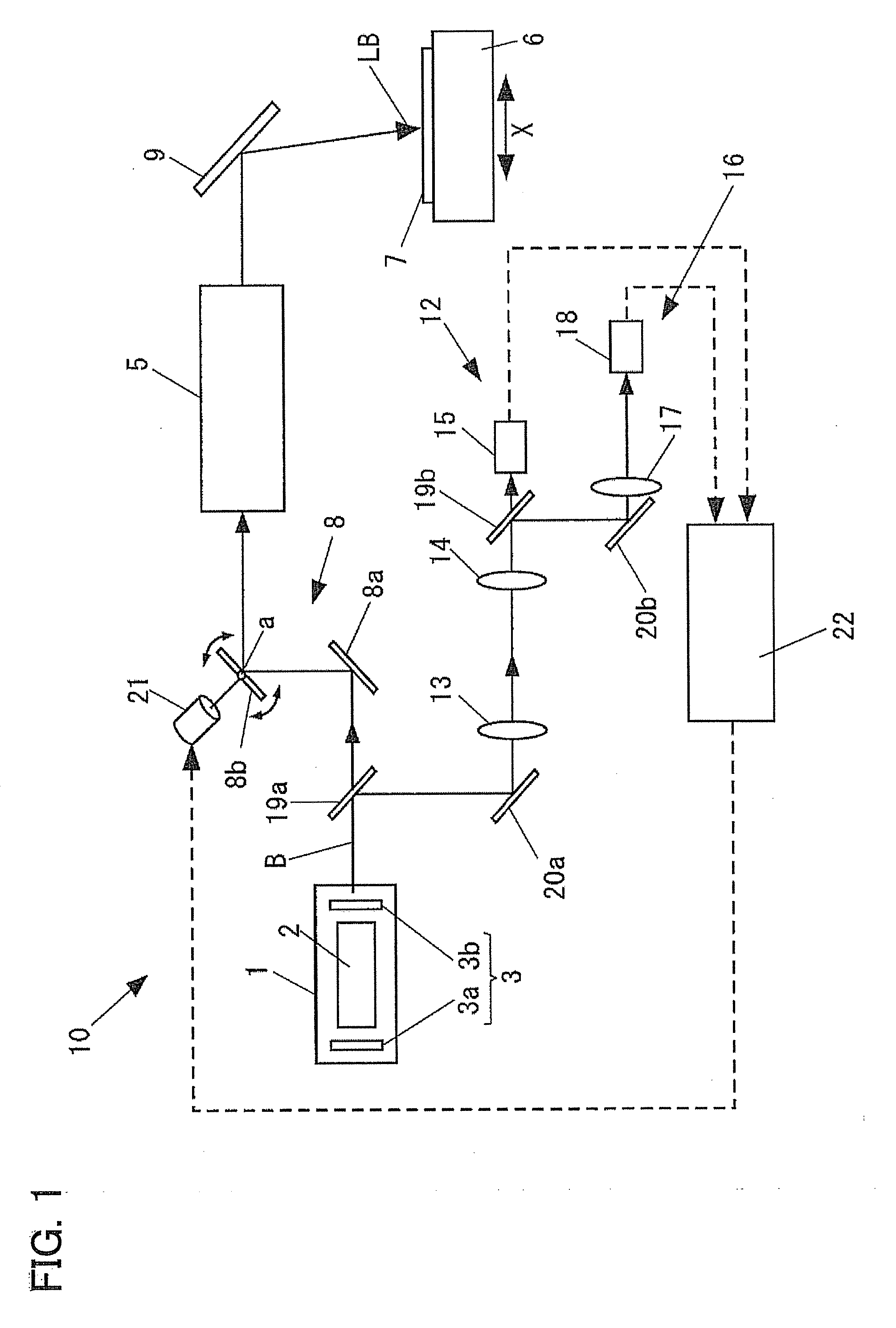
[0030]FIG. 1 illustrates the whole schematic structure of a laser annealing apparatus 10 of the embodiment mode of the present invention. In FIG. 1, the laser annealing apparatus 10 includes a laser 1, an introduction mirror 8, a beam shaping optical system 5, a reflection mirror 9, and a substrate stage 6.

[0031]The laser 1 includes a laser medium 2 and an optical resonator 3. As examples of the laser medium 2, there are a solid-state laser medium, a gas laser medium, and a laser diode. As examples of the solid-state laser medium, there are YAG, YLF, YVO4, and the like. As examples of the gas laser medium, there are excimer, CO2, and the like. The optical resonator 3 includes a pair of reflection mirrors 3a and 3b disposed ...


PUM

PropertyMeasurementUnit
angle deviationaaaaaaaaaa
angle deviation detectoraaaaaaaaaa
angle correction tableaaaaaaaaaa

Abstract

The irradiation unevenness caused by drift occurring in a beam short-axis direction is reduced without adding a new beam shaping unit and affecting the propagation characteristic of a beam in an optical resonator. A position deviation detector for detecting a position deviation of a laser beam before passing through a beam shaping optical system, an angle deviation detector for detecting an angle deviation of the laser beam before passing through the beam shaping optical system, a deflection mirror for deflecting the laser beam, which is disposed in an optical path between a laser and an object (substrate), and a mirror controller for controlling orientation of the deflection mirror, based on detection data obtained using the position deviation detector and the angle deviation detector so as to eliminate the position deviation from a reference irradiation position in the short-axis direction of a linear beam on a surface to be irradiated.

Description

BACKGROUND OF THE INVENTION[0001]1. Field of the Invention[0002]The present invention relates to laser annealing apparatus and method for performing an annealing process on an object to be processed by irradiating the object with a linear beam.[0003]2. Description of the Related Art[0004]In a process for manufacturing thin film transistors used for liquid crystal semiconductor devices, a laser annealing apparatus is used in order to modify a substrate (a semiconductor substrate or a glass substrate) by irradiating the substrate with a laser beam. The modification of the substrate includes crystallization of an amorphous semiconductor thin film such as an amorphous silicon film and activation of impurities added to a semiconductor film.[0005]FIG. 5 is a schematic view of a conventional laser annealing apparatus 30. In the laser annealing apparatus 30, a laser beam 32 emitted from a laser 31 is shaped into a beam with a linear cross section through a beam shaping optical system 33. Th...

Claims


Application Information

Patent Timeline
Patent Type & Authority Applications(United States)
IPC IPC(8): G01J1/20A61N5/00H01L21/268
CPCB23K26/041B23K26/083B23K26/0738B23K26/042
Inventor KAWAKAMI, RYUSUKEKAWAGUCHI, NORIHITO
Owner SEMICON ENERGY LAB CO LTD
Why Eureka
Try Eureka