Method for controlling head and tail shapes of hot-rolled strip steel

A technology for shape control and hot-rolled strip, applied in the field of steel rolling, can solve the problems of untimely metal flow, deterioration of strip shape, strip breakage, etc. The effect of deterioration of shape and reduction of production cost

Active Publication Date: 2013-03-27
ANGANG STEEL CO LTD
View PDF6 Cites 19 Cited by
  • Summary
  • Abstract
  • Description
  • Claims
  • Application Information

AI Technical Summary

Problems solved by technology

[0004] The purpose of the present invention is to provide a method for stably controlling the shape of the strip head and tail plate in the hot continuous rolling and finishing mill, so as to solve the problem of balance and bending in the prior art when the difference between the balance force of the work roll and the force of the bending roll is large. The adverse effect caused by the untimely metal flow in the roll gap caused by the instantaneous switch of the rolls, so as to avoid the deterioration of the shape of the strip head and tail plate and the occurrence of broken strips, etc.

Method used


Image

  • Method for controlling head and tail shapes of hot-rolled strip steel
  • Method for controlling head and tail shapes of hot-rolled strip steel

Examples


Embodiment 1

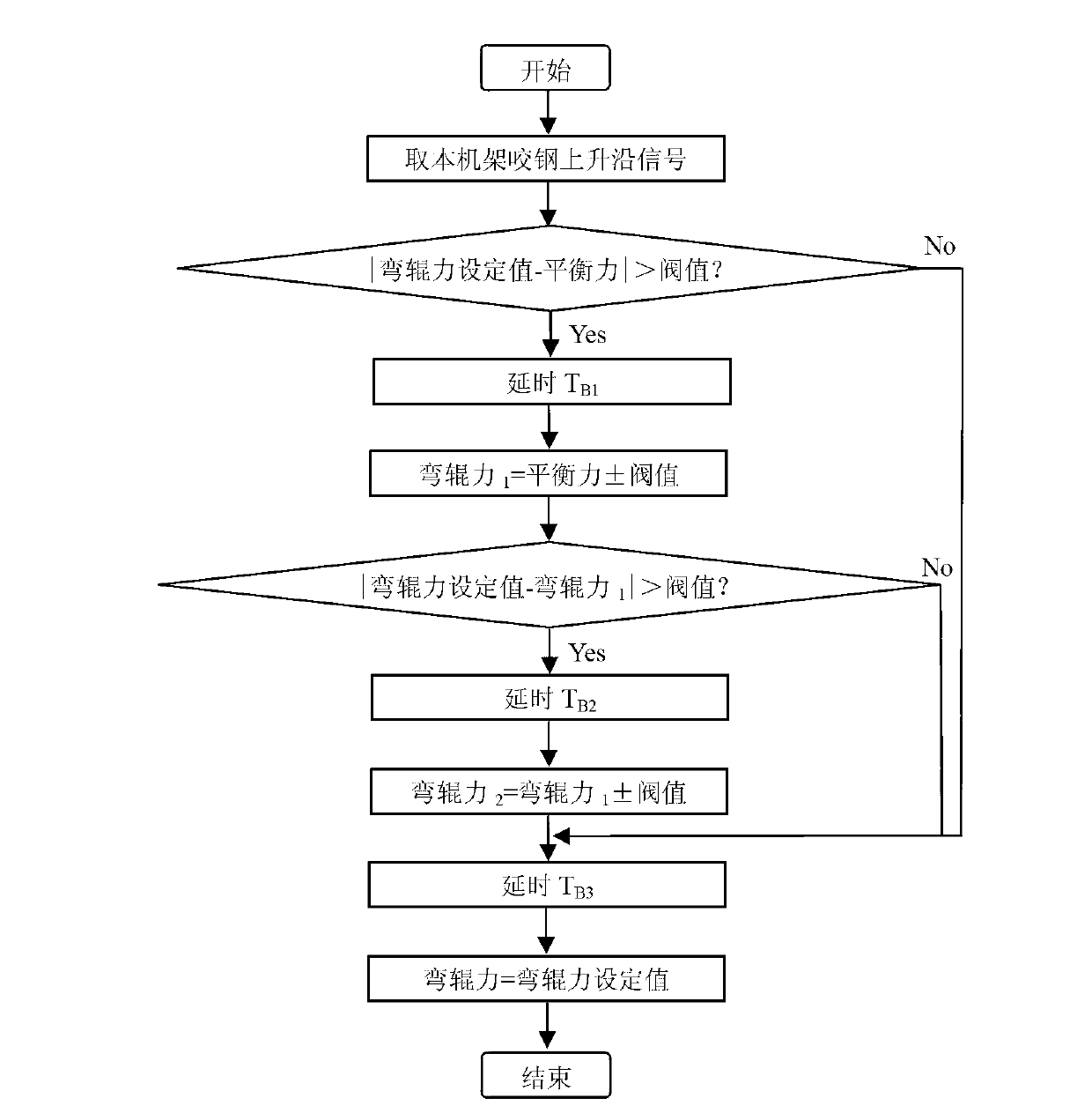
[0024] Take F 7 The balance force is 650KN, the bending force before biting the steel is equal to the balance force, the setting value of the bending force is 1200KN, and the threshold value is 250KN. Depend on figure 1 SHAPE\*MERGEFORMAT The strip head shape control flow chart shows that for the strip head shape control, the specific steps of balancing and bending roll switching are as follows:

[0025] Will F 7 Bite steel rising edge signal is introduced into F 7 The hydraulic roll bending control interface circuit of the frame is used as the control signal, when F 7 Frame hydraulic roll bending control signal received F 7 After the frame bites the steel rising edge signal, first calculate and compare whether the condition of |bending force setting value-balance force|>threshold value is met, that is, |bending force setting value 1200KN-balance force 650KN|>threshold value 250KN , the condition is established, delay 50ms, adjust the balance force to the bending force 1...

Embodiment 2

[0027] Take F 7 The balance force of the frame is 650KN, the setting value of the bending force is 800KN, and the threshold value is 250KN. For strip head shape control, the specific steps of balance and roll bending switching are as follows:

[0028] Will F 7 Bite steel rising edge signal is introduced into F 7 The hydraulic roll bending control interface circuit of the frame is used as the control signal, when F 7 Frame hydraulic roll bending control signal received F 7 After the frame bites the steel rising edge signal, first calculate and compare whether it meets the condition of |bending force setting value-balance force|>threshold value, that is, |bending force setting value 800KN-balance force 650KN|threshold is not satisfied, after a delay of 26ms, adjust the balance force 650KN to the set value of bending force 800KN.

Embodiment 3

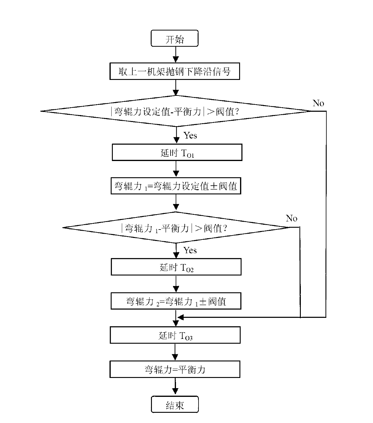
[0030] Take F 7 The balance force of the rack is 650KN, the setting value of the bending force is 1000KN, and the threshold value is 250KN. Depend on figure 2 SHAPE\*MERGEFORMAT The strip tail shape control flow chart shows that for the strip steel tail shape control, the specific steps of balancing and bending roll switching are as follows:

[0031] When F 7 Frame hydraulic roll bending control signal received F 6 After the frame throws the steel falling edge signal, calculate and compare whether the condition of |bending force setting value-balance force|>threshold value is met, that is, |bending force setting value 1000KN-balance force 650KN|>threshold value 250KN, When the condition is established, the delay is 45ms, and the set value of the bending force is adjusted to the bending force 1 , roll bending force 1 It is equal to the set value of bending force ± threshold value. Since the set value of bending force is greater than the balance force, it is taken as a neg...


PUM


Abstract

The invention provides a method for controlling the head and tail shapes of hot-rolled strip steel. For the control on the head shape of strip steel, the smooth switching between the balancing and roll bending of a rack is controlled through a steel biting rising edge signal of the rack; and for the control on the tail shape of the strip steel, the smooth switching between the roll bending and balancing of a follow-up rack is controlled through a steel throwing falling edge signal of an upstream rack. According to the invention, through the reasonable design on a hydraulic balancing and roll bending control scheme of a working roll of a rear finishing mill, phenomena such as the head and tail shapes of strip steel are deteriorated due to the instantaneous switching between balancing and roll bending, and the like can be effectively prevented, thereby improving the quality of head and tail shapes of the strip steel, avoiding the occurrence of creasing and strip breakage accidents, and reducing the production cost.

Description

technical field [0001] The invention belongs to the field of steel rolling, and in particular relates to a method for stably controlling the head and tail shape of a steel strip in a hot continuous rolling finishing mill. Background technique [0002] The roll bending cylinder and balance cylinder of the hot continuous rolling finishing mill work roll are the same hydraulic cylinder. Since the hydraulic cylinder is located between the upper and lower work rolls and is stressed by the work roll chock, the hydraulic work roll bending system of the rolling mill simultaneously It has the functions of bending and balancing. When the rolling mill is unloaded, the hydraulic roll bending system is in a state of balance force. Its main function is to support the weight of the upper roll system, realize the setting of the roll gap, and ensure the contact between the upper working roll and the backup roll when the rolling mill is unloaded; The main function is to change the shape of t...

Claims


Application Information

Patent Timeline
Patent Type & Authority Applications(China)
IPC IPC(8): B21B37/72
Inventor 于斌杨旭郭宝安何士国马荣材刘金超
Owner ANGANG STEEL CO LTD
Why Eureka
Try Eureka