Arc swinging device applied to automatic metal welding

An automatic welding and metal technology, applied in the field of swinging arc device, can solve the problems of difficult control, complex structure, difficult maintenance, etc., and achieve the effect of convenient welding seam width, simple adjustment and control, convenient disassembly and maintenance

Active Publication Date: 2015-04-01
CHANGZHOU JIAZHUO SPECIAL VEHICLES +1
View PDF5 Cites 0 Cited by
  • Summary
  • Abstract
  • Description
  • Claims
  • Application Information

AI Technical Summary

Problems solved by technology

[0003] At present, one type of arc swing device on metal automatic welding equipment uses a servo motor to drive a rack and pinion transmission mechanism, or a servo motor to drive a bevel gear pair transmission mechanism, and controls the swing of the welding torch through a servo motor to drive a gear transmission mechanism. The above structure is complicated. In particular, there is a transmission gap, and the servo motor needs to rotate forward and reverse alternately when swinging the arc, which is not only difficult to control, but also has extremely high requirements on the performance and life of the motor, and the manufacturing cost is high
Another structure of arc swing device is to use magnetic control arc swing, its structure and control are more complicated, maintenance is difficult, and the cost is high
Furthermore, the swing amplitude of most current swing arc devices is fixed, and the weld width cannot be adjusted, so it cannot be applied to metal welding under different working conditions.

Method used


Image

  • Arc swinging device applied to automatic metal welding
  • Arc swinging device applied to automatic metal welding
  • Arc swinging device applied to automatic metal welding

Examples


Embodiment Construction

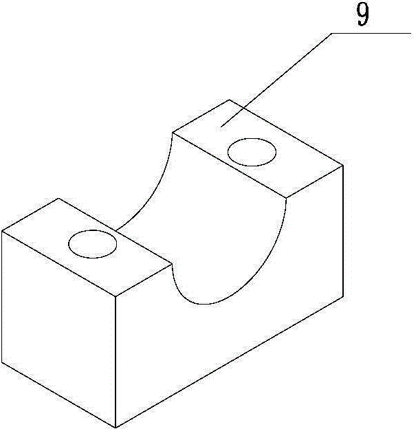
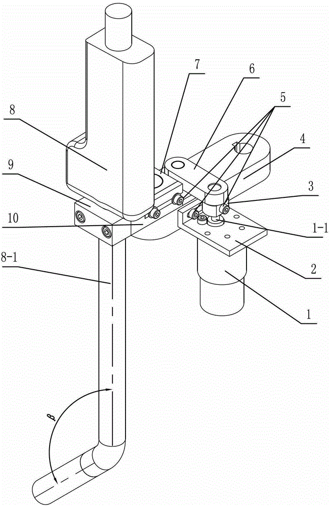
[0020] See figure 1 As shown, the swing arc device for automatic metal welding of the present invention includes a welding torch 8, a swing arc crank linkage mechanism, and a welding torch clamping and welding seam width adjusting mechanism.

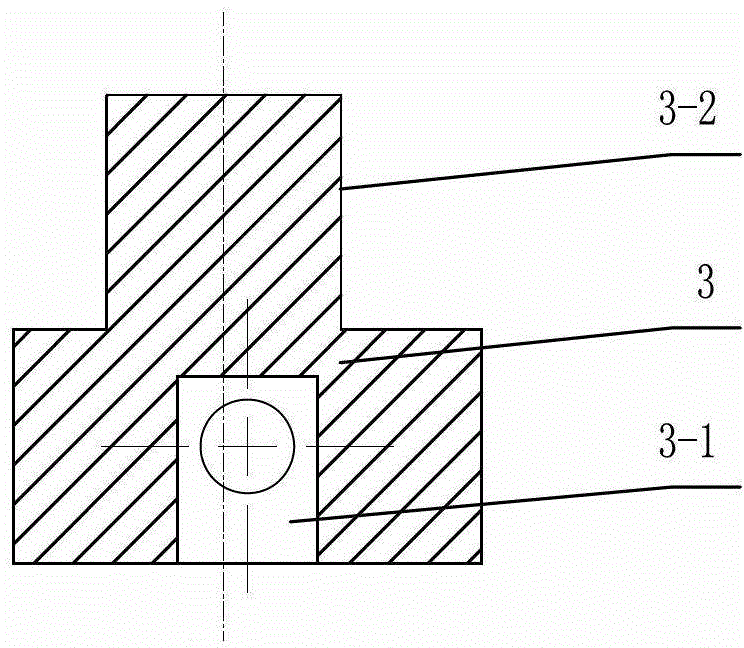
[0021] See Figure 1-4 As shown, the swing arc crank linkage mechanism of the present invention includes a base plate 4, a DC motor 1, an eccentric wheel 3, a connecting rod 6, and a swing guide plate 7. The DC motor 1 is connected to the base plate 4, and the DC motor 1 can adopt a deceleration mechanism. DC motors, see figure 1 As shown, the DC motor 1 of the present invention is installed on the angular motor base 2, and the other side of the motor base 2 is installed on the base plate 4 by a fastener 5, and the output shaft 1-1 of the DC motor 1 and the eccentric wheel 3 Connected, the two sides of the connecting rod 6 are respectively hinged on the eccentric wheel 3 and the swing guide plate 7, and the direct current motor 1 drive...


PUM

PropertyMeasurementUnit
lengthaaaaaaaaaa

Abstract

The invention relates to an arc swinging device applied to automatic metal welding. The arc swinging device comprises a welding gun, an arc swinging crank connecting rod mechanism and a welding gun clamping and weld width adjusting mechanism, wherein the arc swinging crank connecting rod mechanism comprises a base plate, a direct-current motor, an eccentric gear, a connecting rod and a swinging guide plate; the direct-current motor is connected with the base plate; the output shaft of the direct-current motor is connected with one side of the eccentric gear; two sides of the connecting rod are respectively hinged with the eccentric gear and the swinging guide plate; the swinging guide plate is fixed on the base plate; the welding gun clamping and weld width adjusting mechanism comprises a sliding plate and a clamping block; the gun stem of the welding gun is installed between the sliding plate and the clamping block and can be axially adjusted; the sliding plate is adjustably installed on the swinging guide plate; and weld width indication lines are arranged on the swinging guide plate and the sliding plate. The arc swinging device has the characteristics of being reasonable and simple in structure, convenient to repair, low in manufacturing cost and easy to control.

Description

technical field [0001] The invention relates to an arc swing device for automatic metal welding, which belongs to the technical field of automatic welding. Background technique [0002] In recent years, with the development of digitization, automation, computer and mechanical design technology, and the high emphasis on welding quality, automatic metal welding has developed into an advanced manufacturing technology, and automatic welding equipment has played an important role in the application of various industries The role is getting bigger and bigger, and the scope of application is expanding rapidly. In modern industrial production, the mechanization and automation of the welding production process is an inevitable trend in the modernization of the welding mechanism manufacturing industry. [0003] At present, one type of arc swing device on metal automatic welding equipment uses a servo motor to drive a rack and pinion transmission mechanism, or a servo motor to drive a...

Claims


Application Information

Patent Timeline
Patent Type & Authority Patents(China)
IPC IPC(8): B23K9/022
Inventor 李雷刚冯宝林时张杰牛晓庆周珉代华亮姜涛胡晓娟
Owner CHANGZHOU JIAZHUO SPECIAL VEHICLES
Why Eureka
Try Eureka