Supercharge Your Innovation With Domain-Expert AI Agents!

Multi-chamber carbon anode

A carbon anode and anode technology, applied in the field of carbon anode and carbon anode for aluminum electrolysis, can solve the problems of broken anode, insufficient strength, anode bubble pressure drop, etc. the effect of strength

Inactive Publication Date: 2013-03-27
SNTO TECH GRP
View PDF11 Cites 0 Cited by
  • Summary
  • Abstract
  • Description
  • Claims
  • Application Information

AI Technical Summary

Problems solved by technology

Patent No. ZL200520200777.9 discloses a multi-chamber anode. In this technical solution, the grooves are vertical or horizontal, and the depth of the grooves along the vertical direction is 150mm-400mm. The disadvantages of this technical solution are: if The groove is shallow, especially when the groove is only 150mm, the action time to reduce the thickness of the bubble layer is too short, less than 1 / 3 of the anode cycle, if the groove is deep, especially when the groove reaches 400mm, the anode strength Insufficient, in the process of electrolysis, it is easy to break off blocks; the patent application document with the application number 201020194121.1 discloses a multi-chamber anode technology, and the two ends or end faces of the anode described in the application document have upper and lower Through the groove, the disadvantage of this technical solution is that the groove is opened on the end face, which is not conducive to the exhaust in the middle of the anode bottom palm, because the gas generated by the anode during the electrolysis process is mainly distributed in the middle of the anode bottom palm, and the gas at both ends The amount of distribution is less; after the through groove is opened, the strength of the anode is affected. In the process of electrolysis, the anode is prone to broken pieces
[0003] In summary, the existing anode technology has defects such as poor exhaust, high pressure drop of anode bubbles, and insufficient strength.

Method used


Image

  • Multi-chamber carbon anode
  • Multi-chamber carbon anode
  • Multi-chamber carbon anode

Examples


Embodiment 1

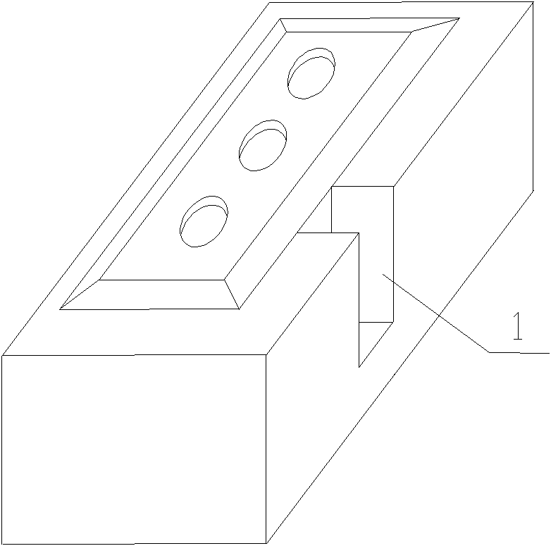
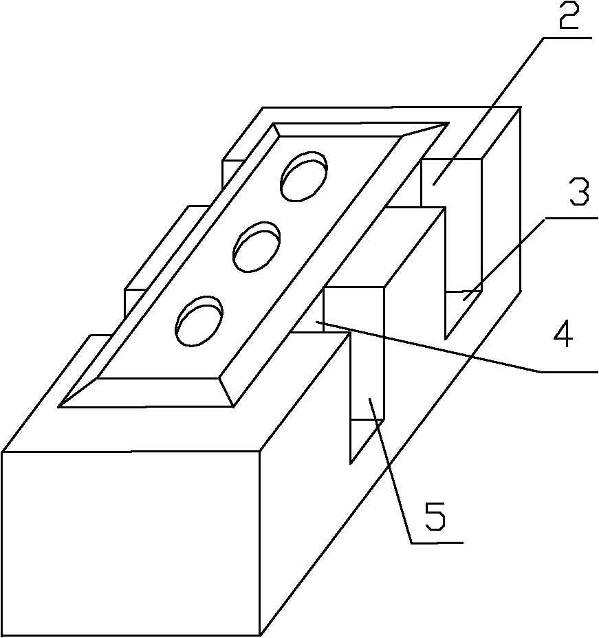
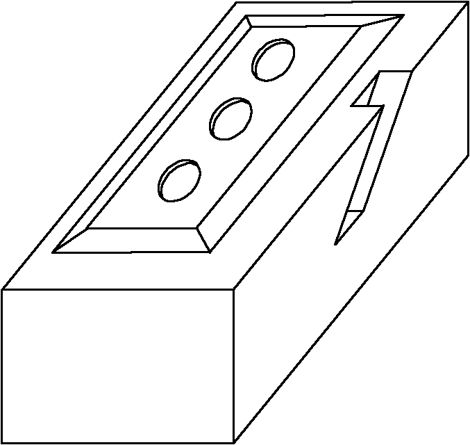
[0023] Such as figure 1 As shown, a multi-chamber carbon anode includes two sides, each of which includes two longest ribs, and is perpendicular to the bottom surface of the anode, and there is a vertical non-through groove 1 on the side of the anode, consisting of Each surface of the groove can be flat or curved. This groove can also be located on the other side parallel to this side. No matter which side the groove can be located at any position on the side of the anode, but the best position is located in the middle area of ​​the side of the anode, the minimum distance from the left edge of the middle area to the left end of the anode is 1 / 10 of the length of the anode , the minimum distance from the right edge to the right end of the anode is 1 / 10 of the anode length. In order to ensure unobstructed exhaust and anode strength more effectively, the groove can be made as a groove with the upper port 2 wider than the lower port 3, or a groove with the opening 5 wider than t...

Embodiment 2

[0025] Such as figure 1 As shown, a multi-chamber carbon anode includes two sides, each of which includes two longest ribs, and is perpendicular to the bottom surface of the anode, and there is a vertical non-through groove 1 on the side of the anode, consisting of Each surface of the groove can be flat or curved. This groove can also be located on the other side parallel to this side. No matter which side the groove can be located at any position on the side of the anode, but the best position is located in the middle area of ​​the side of the anode, the minimum distance from the left edge of the middle area to the left end of the anode is 1 / 5 of the length of the anode , the minimum distance from the right edge to the right end of the anode is 1 / 10 of the anode length. In order to ensure unobstructed exhaust and anode strength more effectively, the groove can be made as a groove with the upper port 2 wider than the lower port 3, or a groove with the opening 5 wider than th...

Embodiment 3

[0027] Such as figure 1 As shown, a multi-chamber carbon anode includes two sides, each of which includes two longest ribs, and is perpendicular to the bottom surface of the anode, and there is a vertical non-through groove 1 on the side of the anode, consisting of Each surface of the groove can be flat or curved. This groove can also be located on the other side parallel to this side. No matter which side the groove can be located at any position on the side of the anode, but the best position is located in the middle area of ​​the side of the anode, the minimum distance from the left edge of the middle area to the left end of the anode is 1 / 10 of the length of the anode , the minimum distance between the right edge and the right end of the anode is 1 / 5 of the anode length. In order to ensure unobstructed exhaust and anode strength more effectively, the groove can be made as a groove with the upper port 2 wider than the lower port 3, or a groove with the opening 5 wider tha...


PUM

PropertyMeasurementUnit
widthaaaaaaaaaa

Abstract

The invention belongs to the technical field of carbon anode used in aluminum electrolysis, and especially relates to a multi-chamber carbon anode. The invention aims at solving a technical problem of providing a multi-chamber carbon anode with smooth exhaust recesses, reduced bottom palm pressure, and uninfluenced application strength. A technical scheme adopted by the invention is that: a multi-chamber carbon anode is provided; at least one side of the multi-chamber carbon anode is provided with vertical or inclined non-penetrating recesses, wherein the number of the non-penetrating recesses is at least one. The multi-chamber carbon anode has the advantages that: 1, the non-penetrating recesses are positioned at the side of the anode, such that exhaust channels are formed, gas-bubble smooth discharging is facilitated, and anode gas-bubble pressure drop is greatly reduced; 2, when electrolysis is carried out on anode bottom, a gas-bubble production amount is relatively low, and influences upon electrolysis and especially energy consumption are relatively small. Therefore, non-penetrating recesses are selected, such that gas discharging is not influenced, anode strength is ensured, and a breaking phenomenon when the anode participates in production is avoided.

Description

technical field [0001] The invention belongs to the technical field of carbon anodes for aluminum electrolysis, in particular to a carbon anode with multiple chambers on its side. Background technique [0002] The carbon anode is the heart of the electrolytic cell. The carbon anode has a crucial impact on whether the various parameters of the electrolysis can meet the standards. The effect in terms of energy saving and consumption reduction is particularly obvious. produce large amounts of CO 2 Gas, if the carbon anode used is an anode without a chamber, most of these gases are difficult to overflow and accumulate at the bottom of the anode. When these gases accumulate to a certain extent, a bubble layer will be formed at the bottom of the anode. The air bubble layer cannot conduct electricity, thereby increasing the resistance, and the power consumption also increases with the increase of resistance. For this reason, multi-chamber anodes have emerged. Patent No. ZL200520...

Claims


Application Information

Patent Timeline
Patent Type & Authority Applications(China)
IPC IPC(8): C25C3/12
Inventor 张煜曾敦伟杜志军高小明叶武龙
Owner SNTO TECH GRP
Features
  • R&D
  • Intellectual Property
  • Life Sciences
  • Materials
  • Tech Scout
  • Unparalleled Data Quality
  • Higher Quality Content
  • 60% Fewer Hallucinations
Learn More