
Chain driving reversing device and method of beam-pumping unit

A technology of beam pumping unit and reversing device, which is applied to transmission device, earthwork drilling, mechanical equipment and other directions, can solve the problems of complex processing, low load rate, low stroke, etc., and achieves good motion balance, The effect of small energy loss and small impact

Inactive Publication Date: 2013-03-27
孙继辉 +1
View PDF12 Cites 1 Cited by
  • Summary
  • Abstract
  • Description
  • Claims
  • Application Information

AI Technical Summary

Problems solved by technology

This balancing method reduces the dynamic load and vibration of the pumping unit, but the precision of the device is high and the processing is complicated
[0003] Through the investigation of ordinary beam pumping units and the comprehensive comparison and analysis of various existing beam pumping units, it is found that ordinary beam pumping units have some shortcomings: the beam of beam pumping units —The connection of the connecting rod-crank reversing mechanism is rigid, so the dynamic load is large and causes energy loss due to impact, and the movement balance is poor; the beam pumping unit is a device with large inertia, and the direct start method with load is adopted when starting , such a starting method requires a large starting torque; the transmission angle of the beam pumping unit fluctuates greatly during operation, and it cannot guarantee that the transmission angle at each position is close to 90 0 , so the crank force is large and uneven, resulting in large torque at the suspension point and sharp peak fluctuations; in terms of installed power, the beam pumping unit has a large torque peak value, in order to ensure the normal operation of the pumping unit, and has enough Overload capacity, it is necessary to choose a larger power motor and a high torque reducer
This large motor and large peak current matching scheme will inevitably lead to an increase in the loss of the motor itself and the circuit loss, and the motor load is extremely mismatched. This is commonly known as the phenomenon of "big horse and small cart", which makes the motor run In most cases, it is in a light load state, the load rate is very low, and the operating efficiency and power factor of the motor are also very low, which not only consumes a lot of energy, but also causes the power supply quality of the grid to deteriorate; the reversing mechanism of the beam pumping unit The transmission ratio is 1, it is difficult to achieve low stroke times

Method used


Image

  • Chain driving reversing device and method of beam-pumping unit
  • Chain driving reversing device and method of beam-pumping unit
  • Chain driving reversing device and method of beam-pumping unit

Examples


Embodiment Construction

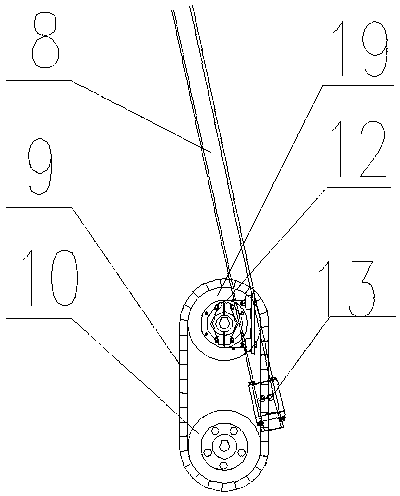
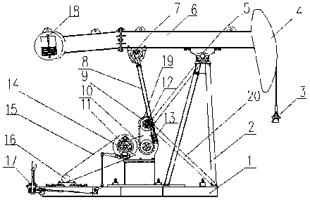
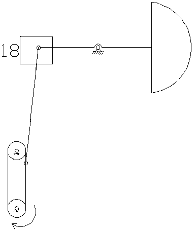
[0024] combined with Figure 1-3 , further describe the beam pumping unit chain drive reversing device mentioned in the present invention:

[0025] The beam-pumping unit chain transmission reversing device of the present invention: includes main transmission gear 10, driven gear 19, transmission chain 9, connecting rod 8, special chain link 21, special chain link fixing device 13, driven gear bearing Seat 12, driven gear shaft 22, the main transmission gear 10 is installed on the output shaft of reduction box 14, driven gear 19 is installed by driven gear shaft 22, driven gear bearing seat 12, driven gear fixed bracket 20 Directly above the driving gear 10, the driven gear bearing seat 12 is in the middle of the driven gear shaft 22. A part of the driven gear fixing bracket 20 is fixed on the bracket 2, and a part is fixed on the base 1. The main transmission gear 10 and the driven gear Moving gear 19 is connected by transmission chain 9, and transmission chain 9 is provi...


PUM


Abstract

The invention relates to a chain driving reversing device and method of a beam-pumping unit. The technical scheme is that a main transmission gear is installed on an output shaft of a reducer box, and a driven gear is installed right above the driving gear through a driven gear shaft, a driven gear bearing base and a driven gear fixing support, wherein the driven gear bearing base is installed right in the middle of the driven gear shaft, a part of the driven gear fixing support is fixed on a support, another part of the driven gear fixing support is fixed on a base, the main driving gear is connected with the driven gear through a transmission chain, special chain links are arranged on the transmission chain, and a special chain link is connected with a connection rod through a fixing bolt on the special chain link fixing device. The chain driving reversing device and method has the advantages that compared with the beam-pumping unit of the same type with the beam-pumping unit of an installation chain transmission reversing device, the loading effect is reduced, the energy saving effect is remarkable, the transmission ratio of the chain transmission reversing device is larger than 1 and can reach as high as 4-7, and compared with a conventional beam-pumping unit, low frequency of stroke can be achieved easily.

Description

technical field [0001] The invention relates to a reversing device for an oil pumping unit, in particular to a chain drive reversing device and a reversing method for a beam pumping unit. Background technique [0002] The beam pumping unit is mainly composed of four parts: beam-connecting rod-crank mechanism, reduction box, power equipment and auxiliary equipment. When working, the transmission of the motor becomes the up and down movement of the donkey head through the reduction box and the crank connecting rod mechanism, and the donkey head passes through the polished rod and the sucker rod to drive the plunger of the deep well pump to move up and down, so that the crude oil in the well is continuously pumped out of the wellbore . Its characteristics are: the beam adopts box-type or I-shaped steel structure, which has high strength, good rigidity and large bearing capacity; Long service life; the donkey head can be turned up, hung up or turned sideways; the brake ado...

Claims


Application Information

Patent Timeline
Patent Type & Authority Applications(China)
IPC IPC(8): F16H37/12E21B43/00
Inventor 孙继辉胡琳杨长军倪水
Owner 孙继辉
Learn More