Transmission and air-drying structure of polycrystalline silicon wafer flocking machine

A technology of polycrystalline silicon wafers and transmission structures, which is applied in the manufacturing of final products, sustainable manufacturing/processing, electrical components, etc., can solve the problems of small contact area between polycrystalline silicon wafers and rollers, affecting the appearance qualification rate of polycrystalline silicon wafers, and improve the appearance qualification. rate effect

Active Publication Date: 2015-07-08
NANTONG SHENGYANG ELECTRIC CO LTD
View PDF4 Cites 0 Cited by
  • Summary
  • Abstract
  • Description
  • Claims
  • Application Information

AI Technical Summary

Problems solved by technology

[0002] Texturing production of polysilicon solar cells generally adopts polysilicon wafers texturing machine, polysilicon wafers texturing machine has texturing tank, alkali pool, ventilation, polysilicon wafers texturing The transmission and air-drying structure of the machine includes rollers and upper air knives. The middle part of each transmission shaft protrudes outwards along the circumferential direction to form rollers. The axial length of the rollers does not exceed the side length of the polysilicon wafer. Each protruding outward in the direction forms a circle for supporting the edge of the polysilicon wafer. The transmission method adopts a chain transmission, and multiple transmission shafts are arranged in parallel and rotate. The polysilicon wafer is placed on the roller and is driven. After passing through the texturing tank and alkali pool, an upper air knife located above the roller is set between the texturing tank and the alkali pool to dry the remaining chemical liquid on the surface of the polysilicon wafer. Since the upper air knife cannot blow to the lower surface of the polysilicon wafer, Therefore, the chemical reaction will continue to occur on the lower surface of the polysilicon wafer, the contact area between the polysilicon wafer and the roller is small, and the liquid medicine in the contacting place will be relatively less than that in other places on the lower surface. During the period from the tank to the alkaline pool, the chemical reaction on the lower surface where there is a lot of liquid medicine is more than the chemical reaction at the contact between the polysilicon wafer and the roller, and an obvious roller mark will be formed on the lower surface of the polysilicon wafer, which affects the polysilicon wafer. Appearance qualified rate after manufacture

Method used


Image

  • Transmission and air-drying structure of polycrystalline silicon wafer flocking machine
  • Transmission and air-drying structure of polycrystalline silicon wafer flocking machine

Examples


Embodiment Construction

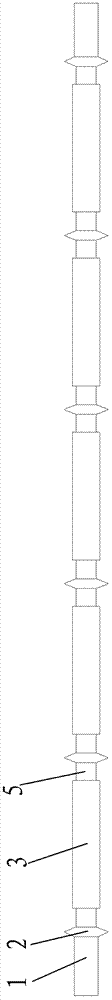
[0010] The structure of the present invention will be further described below in conjunction with the accompanying drawings.

[0011] see figure 1 As shown, the transmission shaft 1 can rotate continuously. In practice, multiple rows of parallel transmission shafts with the same height are arranged to drive the polysilicon wafer forward when rotating. Connecting joints such as 2 are evenly arranged in the axial direction of the transmission shaft 1. Sections such as 2 separate the transmission shaft 1 into a plurality of equal-length transmission shaft segments such as 5, and the middle part of each transmission shaft segment such as 5 protrudes outwards along the circumferential direction to form rollers such as 3, and the rollers such as 3 The axial length is greater than the side length of the polysilicon wafer, so that the long-line contact between the rollers such as 3 and the polysilicon wafer has changed the traditional way of supporting and driving the polysilicon...


PUM


Abstract

The invention discloses a transmission and air-drying structure of a polycrystalline silicon wafer flocking machine. The transmission and air-drying structure comprises a rotatable transmission shaft, joints, rollers and downwind openings. The joints are equidistantly arranged along the axial direction of the transmission shaft, radial sizes of the joints are identical, the middle of a connecting shaft section between each two joints is circumferentially protruded to form the corresponding roller, the axial length of each roller is larger than the side length of a polycrystalline silicon wafer, the circular or long and narrow downwind openings are arranged below the rollers, and the polycrystalline silicon wafer is in linear contact with the rollers. The lower surface of the polycrystalline silicon wafer can be quickly air-dried under the action of air knives blown out from the downwind openings after the polycrystalline silicon wafer is discharged from a flocking groove, roller marks are prevented, and the appearance qualified rate of the manufactured polycrystalline silicon wafer is increased.

Description

technical field [0001] The invention relates to a transmission and air-drying structure of a polycrystalline silicon sheet texturing machine. Background technique [0002] Texture production of polysilicon solar cells generally adopts polysilicon wafer texturing machine, polysilicon wafer texturing machine has texturing tank, alkali pool, ventilation, polysilicon wafer texturing machine transmission and air-drying structure includes rollers, upper air knife, each section of transmission The middle part of the shaft protrudes outward along the circumferential direction to form a roller, the axial length of the roller does not exceed the side length of the polycrystalline silicon wafer, and the two ends of the roller protrude outward along the circumferential direction to form a circle for supporting the polycrystalline silicon wafer The transmission mode adopts a chain transmission, and multiple transmission shafts are arranged in parallel and rotated. The polysilicon wafer i...

Claims


Application Information

Patent Timeline
Patent Type & Authority Patents(China)
IPC IPC(8): H01L31/18
CPCY02P70/50
Inventor 赵春庆蒋剑波莫毓东陆佳佳
Owner NANTONG SHENGYANG ELECTRIC CO LTD
Why Eureka
Try Eureka