Prosthesis for partial replacement of a tubular bone

A prosthetic, tubular technology, applied in the field of prosthetic module system, can solve problems such as narrow application fields, and achieve the effect of small strain

Active Publication Date: 2013-03-27
WALDEMAR LINK GMBH & CO
View PDF9 Cites 10 Cited by
  • Summary
  • Abstract
  • Description
  • Claims
  • Application Information

AI Technical Summary

Problems solved by technology

[0007] A disadvantage of these known prostheses is that they are highly specific to each case (manipulable after surgery, free from rotation, etc.) and thus have only a narrow field of application

Method used


Image

  • Prosthesis for partial replacement of a tubular bone
  • Prosthesis for partial replacement of a tubular bone
  • Prosthesis for partial replacement of a tubular bone

Examples


Embodiment Construction

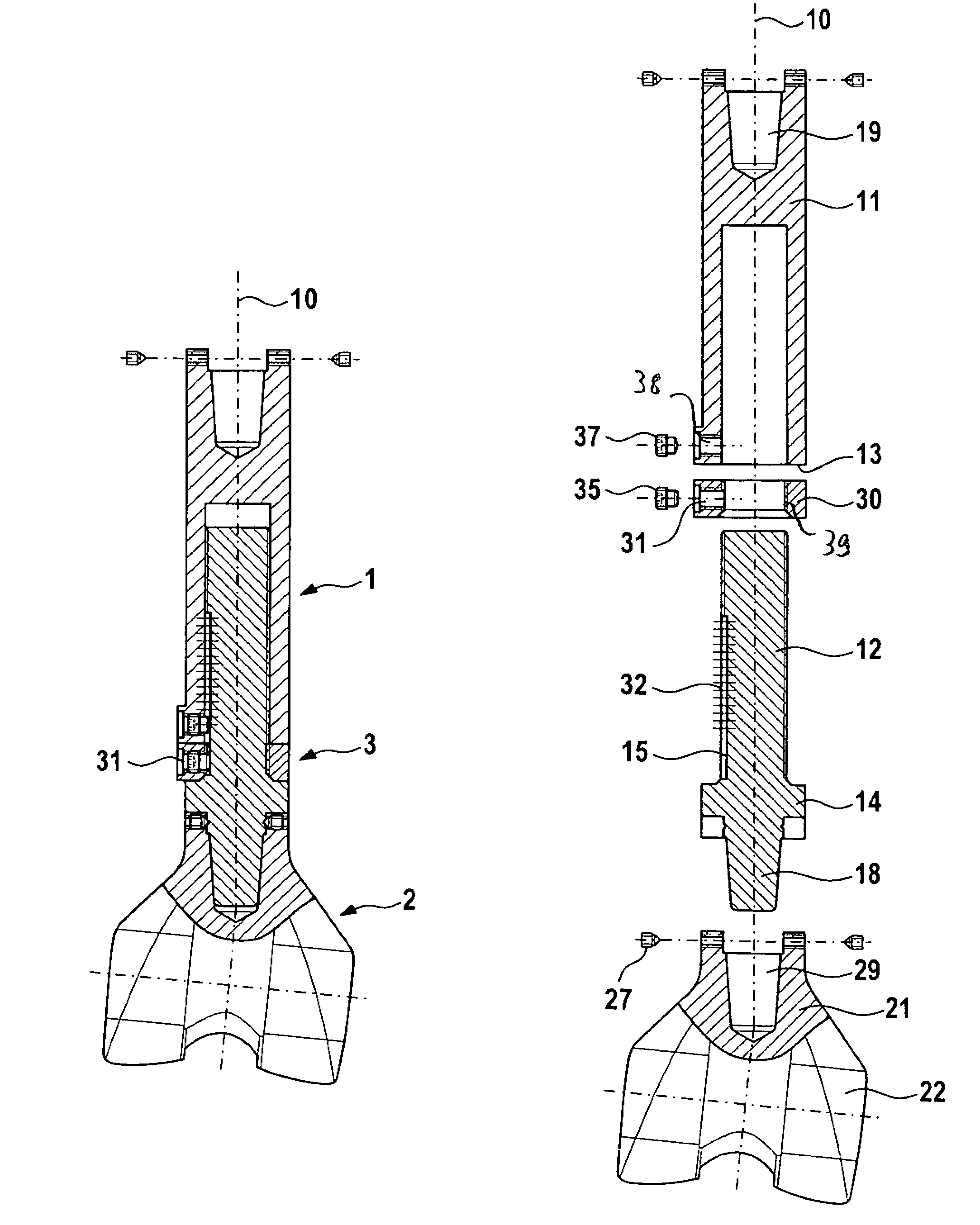
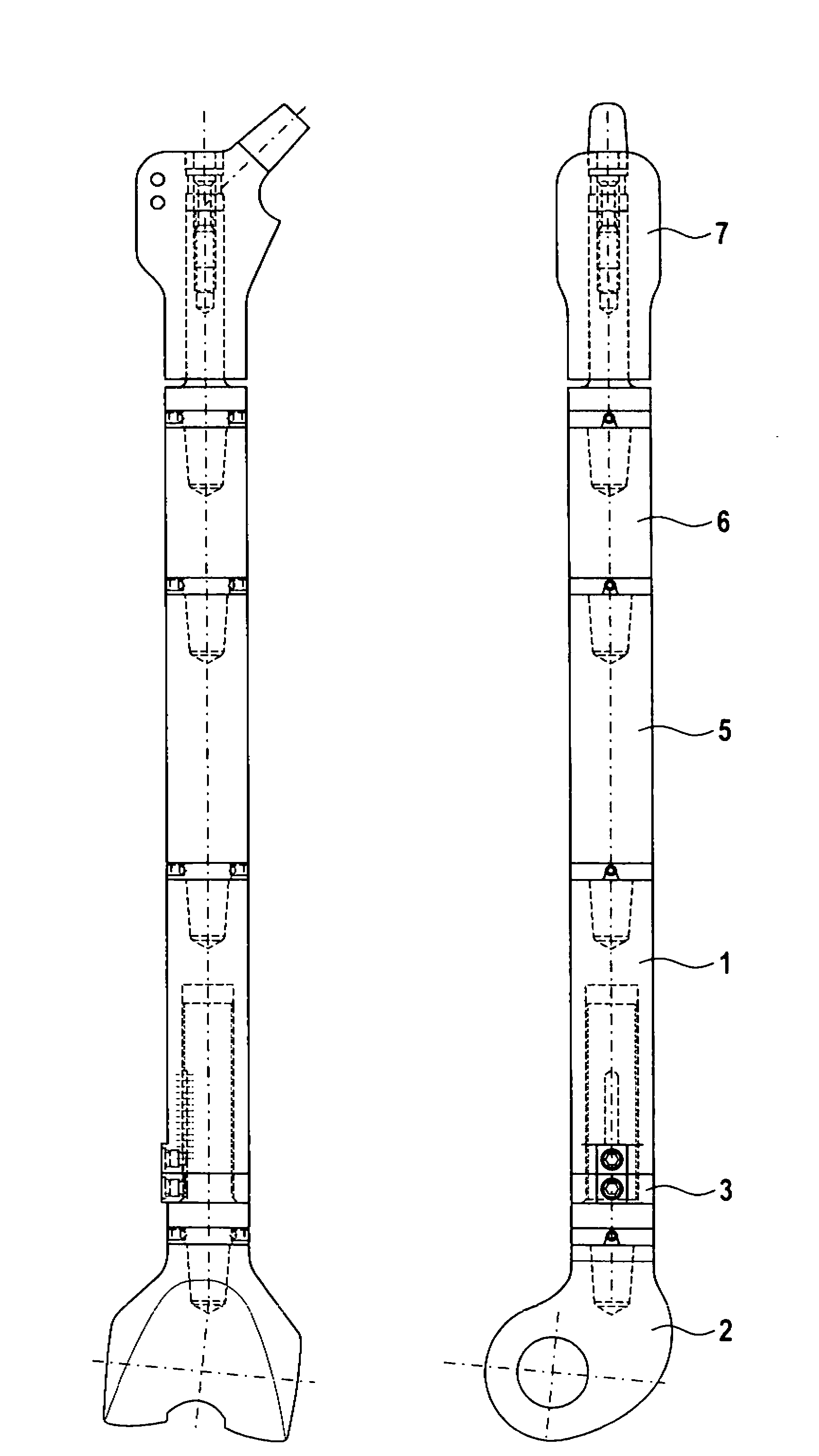
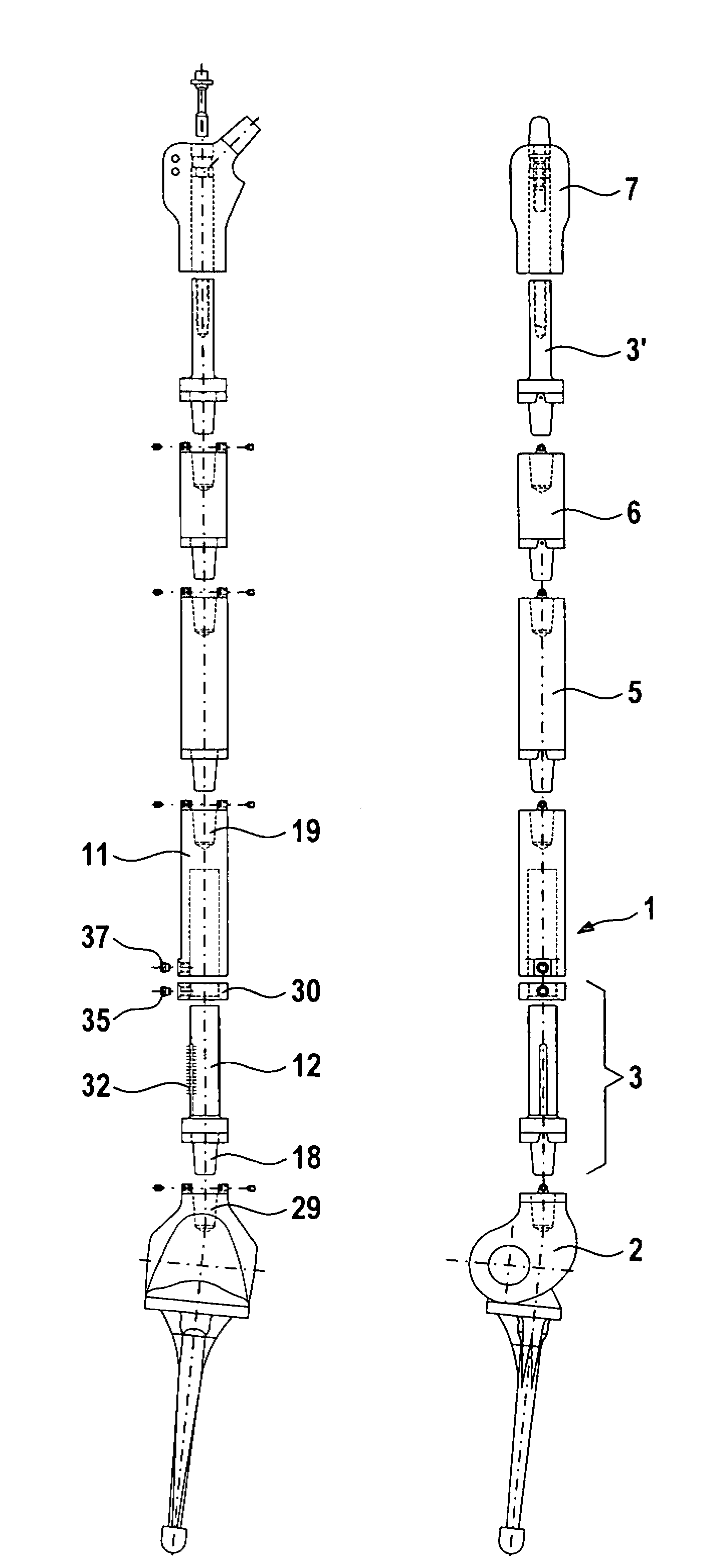
[0047] figure 1 An embodiment of a prosthesis according to the invention is shown, which is intended as an articular prosthesis replacing part of the knee joint and part of the distal femur. As components, it includes a shaft 1 , a joint mechanism 2 and a length adjustment mechanism 3 . The shaft 1 comprises an outer rod 11 and an inner rod 12 guided inside the outer rod 11 for telescopic movement along its central axis 10 . The outer rod 11 has a female conical connection 19 at its first end, which is used to couple other rod parts ( figure 1 not shown in ); it should be noted that it could also be sealed with a blind plug or could be omitted entirely. At its second end, the outer rod has a front flange 13 with a radially oriented front surface. The inner rod 12 has a complementary male connection formation 18 at its first end, which is adapted to engage in a mating female conical connection formation 29 on the articulation mechanism 2 . At the transition to the conical c...


PUM


Abstract

The invention relates to a prosthesis for at least partial replacement of a tubular bone and of an adjacent joint, comprising an elongate shaft (1) with a first end and a second end, and a joint mechanism (2) arranged at the second end of the shaft (1), wherein a length-adjusting mechanism (3) is provided which actuates the shaft (1) along the axis (10) thereof in the manner of a telescope.

Description

technical field [0001] The present invention relates to a prosthesis for replacing at least a portion of tubular bone and adjacent joints. It includes an elongated shaft having first and second ends, and an articulation mechanism disposed at the second end of the shaft. A length adjustment mechanism is provided in the prosthesis, which moves the shaft along its axis in a telescopic manner. The invention also extends to prosthetic modular systems with replaceable shafts. Background technique [0002] Various types of endoprostheses have long been known to replace diseased or defective bones and joints. The use of prosthetics with axes extending beyond the length of the bone to be replaced is used to replace tubular bone, especially in view of neoplastic disease. The shaft replaces and / or augments the diseased or lost bone portion. It is often connected to a joint mechanism that replaces an adjacent joint such as the knee or elbow. The dimensions of the prosthetic shaft m...

Claims


Application Information

Patent Timeline
Patent Type & Authority Applications(China)
IPC IPC(8): A61F2/28A61F2/30A61F2/36A61F2/38
CPCA61F2002/30617A61F2/3607A61F2002/30604A61F2002/30601A61F2002/30332A61F2002/30537A61F2002/3055A61F2002/30495A61F2002/30509A61F2/30A61F2/3859A61F2002/30507A61F2/38A61F2/36A61F2/28
Inventor H·D·林克A·德尼克G·延德罗
Owner WALDEMAR LINK GMBH & CO
Why Eureka
Try Eureka