Synchronizing mechanism of automatic feeder

A technology of synchronous mechanism and automatic feeding, which is applied in the direction of turning equipment, tool holder accessories, metal processing equipment, etc., can solve the problems of complex structure of parts, easy failure, low synchronization, etc., and achieve low drop probability and fast response Fast, highly synchronized effects

Inactive Publication Date: 2013-04-03
何毅
View PDF1 Cites 2 Cited by
  • Summary
  • Abstract
  • Description
  • Claims
  • Application Information

AI Technical Summary

Problems solved by technology

However, the device relies on mechanical action, the structure of the parts is complicated, and it is prone to failure (belt wear, slipping), and the synchronization is low

Method used


Image

  • Synchronizing mechanism of automatic feeder
  • Synchronizing mechanism of automatic feeder

Examples


Embodiment Construction

[0016] Below in conjunction with accompanying drawing description and specific embodiment, the present invention will be described in further detail:

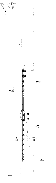
[0017] see Figure 1-Figure 2 , a synchronous mechanism for an automatic feeder, comprising a fixed bracket 1, a linear slide rail 2 and a machine tool connection bracket 4, the linear slide rail 2 is fixed on the fixed bracket 1, and between the machine tool connection bracket 4 and the linear slide rail 2 Connected by the connecting piece 3, the shape of the connecting piece 3 is L-shaped, one side of the connecting piece 3 is fixed on the linear slide rail 2 with a connecting nut, and the other side is fixed on the machine tool connection bracket 4, the linear slide rail 2 A position measuring device 5 is arranged at the bottom, and the position measuring device 5 is a grating ruler displacement sensor, and a data feedback signal line 6 is connected to the position measuring device 5 .

[0018] During installation, the fixe...


PUM


Abstract

The invention provides a synchronizing mechanism of an automatic feeder. The synchronizing mechanism comprises a fixed support, a linear sliding rail and a machine tool attachment bracket, wherein the linear sliding rail is fixed on the fixed support; the machine tool attachment bracket and the linear sliding rail are connected with each other by virtue of a connecting piece; the bottom of the linear sliding rail is provided with a position measuring device; and the position measuring device is connected with a data feedback signal line. The synchronizing mechanism is simple in structure, low in failure rate and low in rod breakage possibility during the synchronization process, and can be used for greatly improving the production efficiency and lowering the production cost.

Description

technical field [0001] The invention relates to a synchronous mechanism, in particular to a synchronous mechanism of an automatic feeding machine. Background technique [0002] The automatic feeding machine is placed at the front end of automatic processing machines such as automatic lathes and lathes. It uses a chuck to clamp the bar and sends the bar into the lathe for processing. Among them, the center type lathe is that the mandrel of the lathe clamps the workpiece for Z-axis movement, and each tool is fed in the XY quadrant at a fixed position. When using the center type lathe, the bar must reciprocate synchronously with the lathe mandrel Otherwise, the bar will be disengaged from the chuck that clamps the bar. Therefore, the existing automatic feeding machine is equipped with a synchronous structure to make the bar move synchronously with the lathe mandrel. [0003] The Chinese patent authorization announcement number is CN 2821283Y, and the utility model patent on Se...

Claims


Application Information

Patent Timeline
Patent Type & Authority Applications(China)
IPC IPC(8): B23B15/00B23B25/06
Inventor 何毅
Owner 何毅
Why Eureka
Try Eureka