Air valve mechanism of carbon arc gouging gun

A technology of carbon arc gouging and air valve, which is applied in the direction of lift valve, sliding valve, valve device, etc., which can solve the problems of insufficient air valve guide area, small air flow, and reduced air flow conduction, so as to ensure product processing Quality, enhance the effect of air conduction volume

Inactive Publication Date: 2013-04-03
浙江长征电影碳棒有限公司
View PDF6 Cites 6 Cited by
  • Summary
  • Abstract
  • Description
  • Claims
  • Application Information

AI Technical Summary

Problems solved by technology

Since the air valve is set in the insulating handle, and the switch of the air valve is controlled by holding both ends of the valve core rod, in order to ensure the convenience and comfort of hand-held switch operation, the diameter of the insulating handle section at the installation position of the air valve should not be too large , must be suitable for hand holding, therefore, the axial length of the valve housing and the length of the valve core rod are limited
The diameters of the air inlet and outlet holes located on both sides of the middle of the valve chamber are fixed. When the air valve is closed, the truncated cone-shaped valve plug section of the valve core rod must have sufficient length to completely seal the air holes on both sides of the valve chamber. , and when the valve is opened, due to the limitation of the length of the valve core rod and the axial length of the valve housing, the truncated cone valve plug section of the valve core rod cannot completely withdraw from the airway position of the valve cavity, so the ring of the valve core rod The ring air guide groove can only partially connect with the air passages on both sides of the valve cavity, thereby reducing the conduction of the air flow, resulting in poor chip removal when the air gouging gun is planing due to insufficient air flow, which seriously affects the use of the gouging gun and product processing quality
In order to improve the above-mentioned problem of small air flow due to insufficient guide area of ​​the air valve, many designers increase the diameter of the air inlet and outlet holes on both sides of the valve cavity to expand the air flow conduction space. However, there is little room for expanding the diameter of the inlet and outlet holes. It will cause the truncated cone valve plug section of the valve core stem to fail to close the air hole and leak air

Method used


Image

  • Air valve mechanism of carbon arc gouging gun
  • Air valve mechanism of carbon arc gouging gun
  • Air valve mechanism of carbon arc gouging gun

Examples


Embodiment Construction

[0014] The present invention will be further described below with reference to the accompanying drawings.

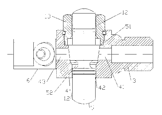
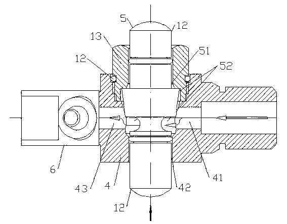
[0015] An air valve mechanism of a carbon arc gouging gun, which has a pressure rod type manual air valve composed of a valve housing 4, a valve cover 13 and a valve core rod 5, and the valve housing 4 is provided with a valve core penetrating through both ends Cavity 42, one end of spool cavity 42 is connected with hollow type bonnet 13 by screw thread, and the middle part of spool cavity is truncated cone shape, is respectively provided with air inlet 41 and on the valve casing of truncated cone shape cavity both sides. The air outlet 43, the air inlet 41 and the air outlet 43 are respectively connected to the air inlet connecting pipe 3 and the air outlet connecting pipe 6, and the air inlet connecting pipe 3 is connected to the external air source pipe 11 and the power lead 10. The valve housing 4 of this embodiment is integrally formed with the air inlet connect...


PUM


Abstract

The invention provides an air valve structure of a carbon arc gouging gun. The air valve structure comprises a pressure rod type manual control air valve formed by a valve casing, a valve cover and a valve core rod, wherein an air inlet half-moon groove and an air outlet half-moon groove are respectively formed at the upper edge part and the lower edge part of an air inlet and an air outlet at two sides of a valve core cavity along the peripheral direction of the inner wall of the valve core cavity. The air valve structure has the beneficial effects that a half-moon air guide slot for connecting the air inlet with the air outlet is skillfully formed in the inner wall of the valve core cavity, so that the air guide amount of the air valve is greatly increased; the air consumption and the airflow pressure of the carbon arc gouging gun can be completely satisfied under the condition of not changing the size of the valve body and not affecting the comfortableness of manually operating the opening and closing of the air valve; the processing quality of products can be ensured; and the problem that the air flow of a pressing handle type manual control air valve is small can be successfully solved.

Description

technical field [0001] The invention relates to an electric arc cutting tool, in particular to an air guiding structure of a carbon arc gouging gun. Background technique [0002] Carbon arc gouging gun is a tool that uses electric arc and compressed air to plan workpieces. It is often used to make U-shaped grooves and weld root cleaning on various steel workpieces. The structure of existing general carbon arc gouging gun is, as attached Figure 1~4 , it has an insulated handle 2, the front end of the insulated handle is connected with a carbon holding clamp 1, and an air storage chamber is provided in the chuck 8 of the lower jaw of the carbon holding clamp, and the side of the chuck 8 is provided with an air storage chamber and connected to the air storage chamber. The air guide hole 7 parallel to the axial direction of the clamping carbon handle, the pressure handle type manual air valve 4 is installed in the insulating handle, the central axis of the valve chamber 42 of t...

Claims


Application Information

Patent Timeline
Patent Type & Authority Applications(China)
IPC IPC(8): B23K9/28B23K9/013F16K1/38
CPCB23K9/013F16K1/38B23K9/28B23K9/32F16K3/22
Inventor 忻建国凌兵
Owner 浙江长征电影碳棒有限公司
Why Eureka
Try Eureka