Stick-slip rotating and positioning device

A positioning device, stick-slip technology, applied in the direction of nanostructure manufacturing, nanotechnology, nanotechnology, etc., can solve the problems of large positioning error, large volume, and the inapplicability of rotary positioning devices, and achieve easy operation, small size, and High applicability effect

Active Publication Date: 2013-04-03
HARBIN INST OF TECH
View PDF2 Cites 2 Cited by
  • Summary
  • Abstract
  • Description
  • Claims
  • Application Information

AI Technical Summary

Problems solved by technology

[0003] In order to solve the problem that the current rotary positioning device cannot be used in ultra-low temperature, ultra-vacuum, high electric field or high magnetic field and other working places, and the rotary positioning device in the prior art has a large volume and large positioning error, it further provides a stick-slip type rotary positioning device

Method used


Image

  • Stick-slip rotating and positioning device
  • Stick-slip rotating and positioning device
  • Stick-slip rotating and positioning device

Examples


specific Embodiment approach 1

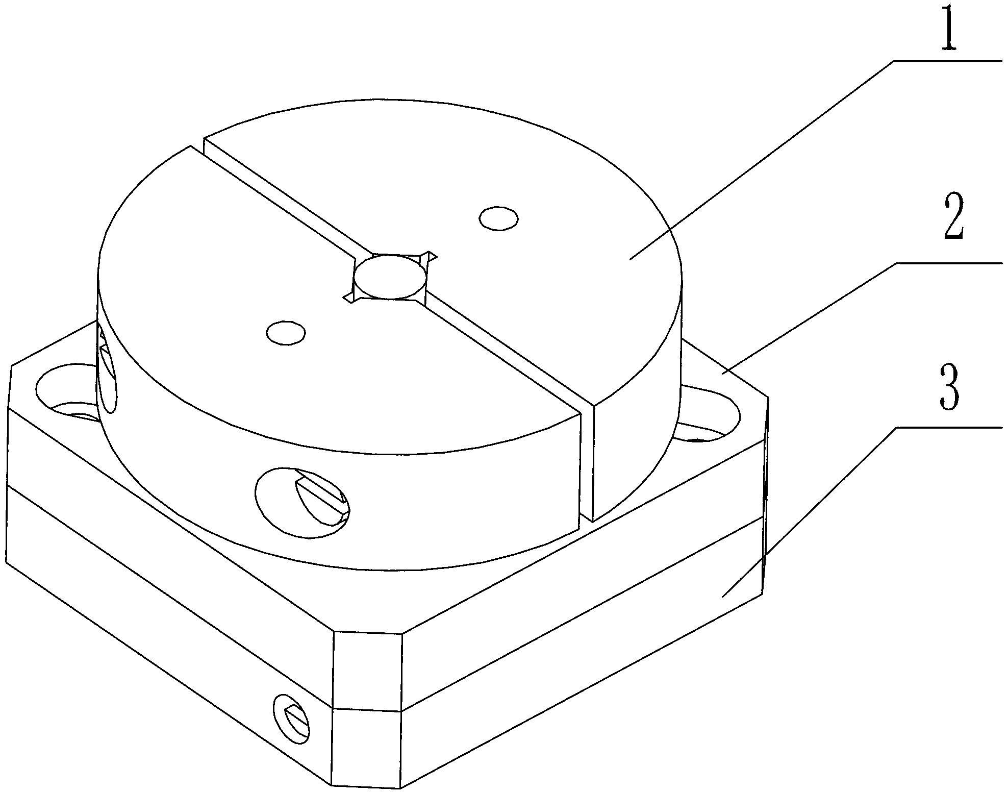
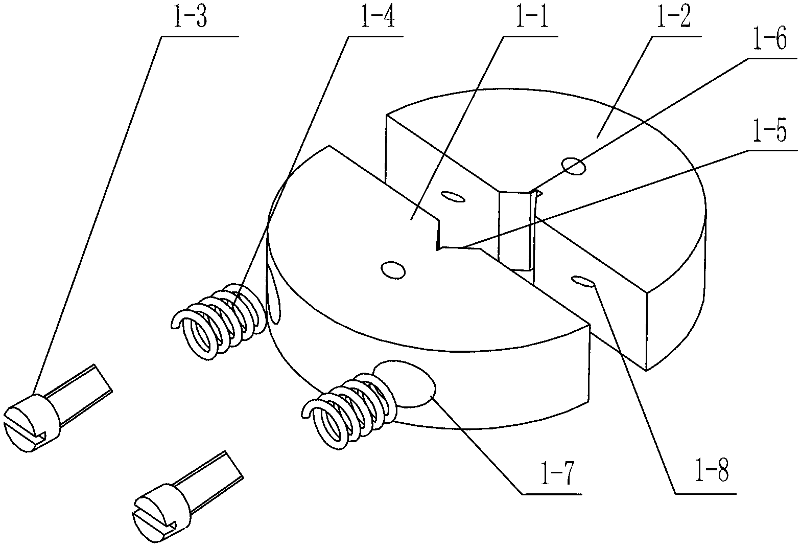
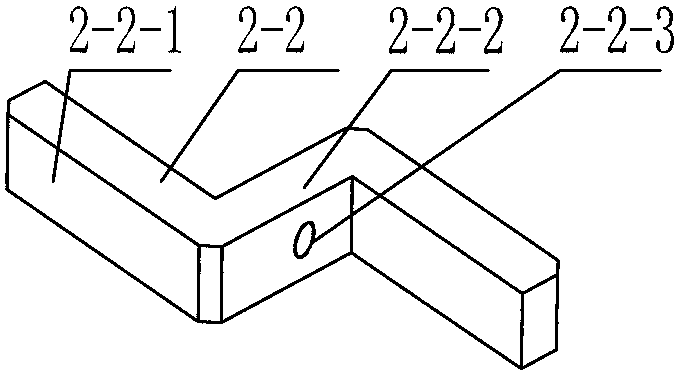
[0008] Specific implementation mode one: combine Figure 1-Figure 13 Describe this embodiment, a stick-slip rotary positioning device, the device includes a rotating unit 1, a drive unit 2 and a base 3; the rotating unit 1 includes a first rotating semicircular table 1-1 and a second rotating semicircular table 1-2 , the driving unit 2 includes a driving elastic table 2-1 and a driving rotating plate 2-2, the base 3 includes a base 3-1 and a piezoelectric ceramic driver 3-2, and the center of the section of the first rotating semicircular table 1-1 is processed with The first V-shaped groove 1-5, the second V-shaped groove 1-6 is processed at the center of the cross section of the second rotating semi-circular platform 1-2, the first rotating semi-circular platform 1-1 and the second rotating semi-circular platform 1-2 are opposite The installation combination is a round table, the first V-shaped groove 1-5 and the second V-shaped groove 1-6 are arranged oppositely, the drivin...

specific Embodiment approach 2

[0011] Specific implementation mode two: combination figure 1 , figure 2 and Figure 8 Describe this embodiment, a stick-slip type rotary positioning device, the first rotary semicircular table 1-1 is processed with two countersunk holes 1-7, the center line of the counterbore 1-7 is aligned with the first rotary semicircular table The straight face on one side of 1-1 is vertical, and two first threaded holes 1-8 are provided on the second rotating semicircular table 1-2, and the two first threaded holes 1-8 are opposite to the two countersunk holes 1-7 The settings are the same as those in the first embodiment.

specific Embodiment approach 3

[0012] Specific implementation mode three: combination figure 1 , figure 2 and Figure 8 Describe this embodiment, a stick-slip rotary positioning device, the device also includes two first adjusting bolts 1-3 and two adjusting springs 1-4, the adjusting springs 1-4 are sleeved on the first adjusting bolts 1- 3 on the screw rod, the adjustment spring 1-4 is installed in the first threaded hole 1-8 through the countersunk hole 1-7, and the two semicircular bodies can be effectively fixed by the adjustment spring 1-4 and the first adjustment bolt 1-3 screw rod, This method can precisely adjust the frictional force between the rotating unit 1 and the rotating shaft 2-1-2 to make the structure compact, and the other is the same as the second embodiment.


PUM


Abstract

The invention relates to a rotating and positioning device, and in particular to a stick-slip rotating and positioning device. The invention aims to solve the problems that the existing rotating and positioning device cannot be used in working occasions of ultralow temperature, ultravacuum, high electric fields or high magnetic fields and the like, and the rotating and positioning device in the prior art is large in size and large in positioning error. The device comprises a rotating unit, a driving unit and a base, wherein the rotating unit comprises a first rotating semicircular table and a second rotating semicircular table; the driving unit comprises a driving elastic table and a driving rotating plate; the base comprises a drill base and a piezoelectric actuator; multiple groups of flexible hinges are processed on the upper end surface of the driving elastic table; a fork structure is arranged at the bottom end surface of the driving elastic table; a driving rotating plate is arranged at the bottom of the fork structure; the driving unit is arranged at the top of the driving elastic table; the driving elastic table is arranged on the drill base; and the piezoelectric actuator is arranged in the drill base. The stick-slip rotating and positioning device is used for micro-nano operation experimental study.

Description

technical field [0001] The invention relates to a rotary positioning device, in particular to a stick-slip rotary positioning device. Background technique [0002] Nano-positioning technology is the basis of nano-operation technology. With the rapid development of nano-technology, more and more application fields require small-sized rotary positioning devices with nano-level positioning accuracy and millimeter-level motion strokes. At present, the existing technology of rotary positioning The application environment of the device is also very extreme, and cannot be used in workplaces such as ultra-low temperature, ultra-vacuum, high electric field or high magnetic field, and the rotary positioning device in the prior art is bulky and has large positioning errors. Contents of the invention [0003] In order to solve the problem that the current rotary positioning device cannot be used in ultra-low temperature, ultra-vacuum, high electric field or high magnetic field and oth...

Claims


Application Information

Patent Timeline
Patent Type & Authority Applications(China)
IPC IPC(8): B82B3/00
Inventor 荣伟彬张世忠聂斌斌周杰李东洁
Owner HARBIN INST OF TECH
Why Eureka
Try Eureka