
Back pressure pure condensation switching heating system

A heating system and pure condensation technology, applied in the field of back pressure pure condensation switching heating system, can solve the problems of low-pressure cylinder conversion mechanical energy efficiency drop, cold source loss, large thermal energy loss, etc., to prevent deformation and increase heat supply , the effect of increasing heat supply

Active Publication Date: 2015-11-18
GUODIAN LONGYUAN ENERGY SAVING TECH
View PDF8 Cites 0 Cited by
  • Summary
  • Abstract
  • Description
  • Claims
  • Application Information

AI Technical Summary

Problems solved by technology

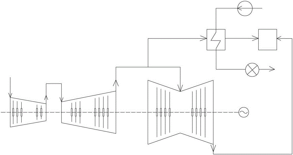
[0003] Conventional heating methods such as figure 1 As shown, the exhaust steam of the medium-pressure cylinder is used as the heating steam source. First, due to the limitation of the minimum flow rate of the low-pressure cylinder, a large proportion of the exhaust steam of the medium-pressure cylinder has to be passed into the low-pressure cylinder, while the rest of the medium-pressure cylinder The amount of steam that can be used for heat is limited, which makes it impossible to obtain huge heating benefits; second, when the flow rate of the low-pressure cylinder drops a lot, especially when the flow rate is lower than the minimum flow rate, the steam does not do work in the low-pressure cylinder, or even negative work. The exhaust steam enthalpy of the low-pressure cylinder is significantly increased, the efficiency of converting mechanical energy of the low-pressure cylinder is reduced, and the proportion of steam converted into electric energy in the low-pressure cylinder is reduced. More than 80% of the steam heat entering the low-pressure cylinder is discharged into the condenser, resulting in the loss of cold source
Therefore, the traditional heating method not only limits the heat supply of the unit, but also has a large heat loss

Method used


Image

  • Back pressure pure condensation switching heating system
  • Back pressure pure condensation switching heating system
  • Back pressure pure condensation switching heating system

Examples


Embodiment Construction

[0018] The specific implementation manners of the present invention will be further described in detail below in conjunction with the accompanying drawings and embodiments. The following examples are used to illustrate the present invention, but not to limit the scope of the present invention.

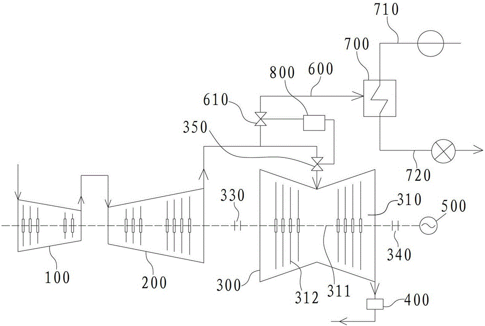
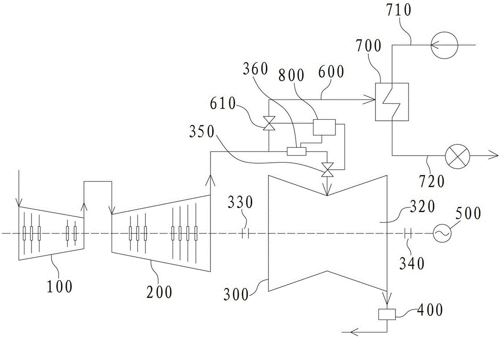
[0019] The present invention mainly innovates the traditional heating method. In the heating period, the pure condensing rotor is set as a back pressure rotor with no impeller and the optical axis is idling, so as to give full play to the advantages of the back pressure rotor in high-efficiency heating. In the non-heating period , the traditional pure condensing rotor is still used, and the heat energy is used for power generation as much as possible without the need for heating. Furthermore, the energy saving effect is improved by switching the back pressure pure condensing. A series of improvements to make the energy saving effect better. Such as figure 2 , 3 Examples of the non-...


PUM


Abstract

The invention provides a back pressure and straight condensing switching heat supply system, which comprises a high-pressure cylinder, a medium-pressure cylinder, a low-pressure cylinder and a condenser which are sequentially communicated, and also comprises a steam extraction pipeline and a heater for heating network, wherein the steam extraction pipeline is respectively communicated with the medium-pressure cylinder and the heater for heating network. The back pressure and straight condensing switching heat supply system is characterized in that in the heating period, a rotor in the low-pressure cylinder is set to be a back pressure rotor, and the back pressure rotor is an optical shaft without an impeller; and in the non-heating period, a low-pressure rotor with an impeller is used to run under the straight condensing condition. Compared with the traditional heat supply system, the back pressure and straight condensing switching system provided by the invention has the advantages that: in the heating period, the heat supply quantity of a unit is greatly increased, the exhaust heat of the medium-pressure cylinder is fully utilized, and the problems that the negative work and the cold source loss of steam are caused by decline in quantity of steam introduced into the low-pressure cylinder in the heating period are solved.

Description

technical field [0001] The invention relates to an energy-saving heat supply system of a power plant, in particular to a back pressure pure condensation switching heat supply system. Background technique [0002] Due to the current coal-fired power inversion phenomenon of high coal price market and low electricity price, thermal power plants generally operate at a loss in power generation. From the point of view of the production process of the thermal power plant, the traditional heat supply uses the exhaust steam of the medium-pressure cylinder as the steam source for heating and heating of residents. According to the analysis of the electrothermal conversion process, the exhaust steam of the medium-pressure cylinder only needs to consume about 40% of the useful energy of steam. The standard coal consumption of the heating unit is only 16.8kg / GJ, while the standard coal consumption of the small boiler heating unit is generally 42kg / GJ. Therefore, it is an effective way fo...

Claims


Application Information

Patent Timeline
Patent Type & Authority Patents(China)
IPC IPC(8): F01K17/02
CPCY02E20/14
Inventor 徐则林张攀李文江张贺
Owner GUODIAN LONGYUAN ENERGY SAVING TECH
Learn More