
Forward low-friction unloading gear for reducing valve and reducing valve

A technology of unloading device and low friction, applied in valve device, valve device for absorbing fluid energy, valve details, etc. It can solve the problem that the pressure reducing valve cannot meet the adjustment accuracy, and reduce the contact area and surface friction of the dynamic seal. coefficient, improve the adjustment accuracy, reduce the effect of dynamic friction

Active Publication Date: 2013-04-03
NO 11 INST OF NO 6 ACADEMY OF CHINA AEROSPACE SCI & TECH
View PDF9 Cites 5 Cited by
  • Summary
  • Abstract
  • Description
  • Claims
  • Application Information

AI Technical Summary

Problems solved by technology

When the engine is working, the inlet pressure continues to decrease with gas consumption. The existing direct-acting pressure reducing valve is affected by the inlet pressure change, and the outlet pressure adjustment accuracy is basically within ±10%.
In order to meet the thrust precision requirements, the system proposes a ±5% adjustment requirement for the pressure reducing valve through adjustment calculation and pressure coordination analysis. When the inlet pressure varies from 23.5MPa to 3.6MPa, the direct acting pressure reducing valve cannot meet the adjustment accuracy Requirements, in order to solve the above problems, a positive low-friction unloading device that can improve the adjustment accuracy of the pressure reducing valve is proposed. Adjustment accuracy

Method used


Image

  • Forward low-friction unloading gear for reducing valve and reducing valve
  • Forward low-friction unloading gear for reducing valve and reducing valve
  • Forward low-friction unloading gear for reducing valve and reducing valve

Examples


Embodiment Construction

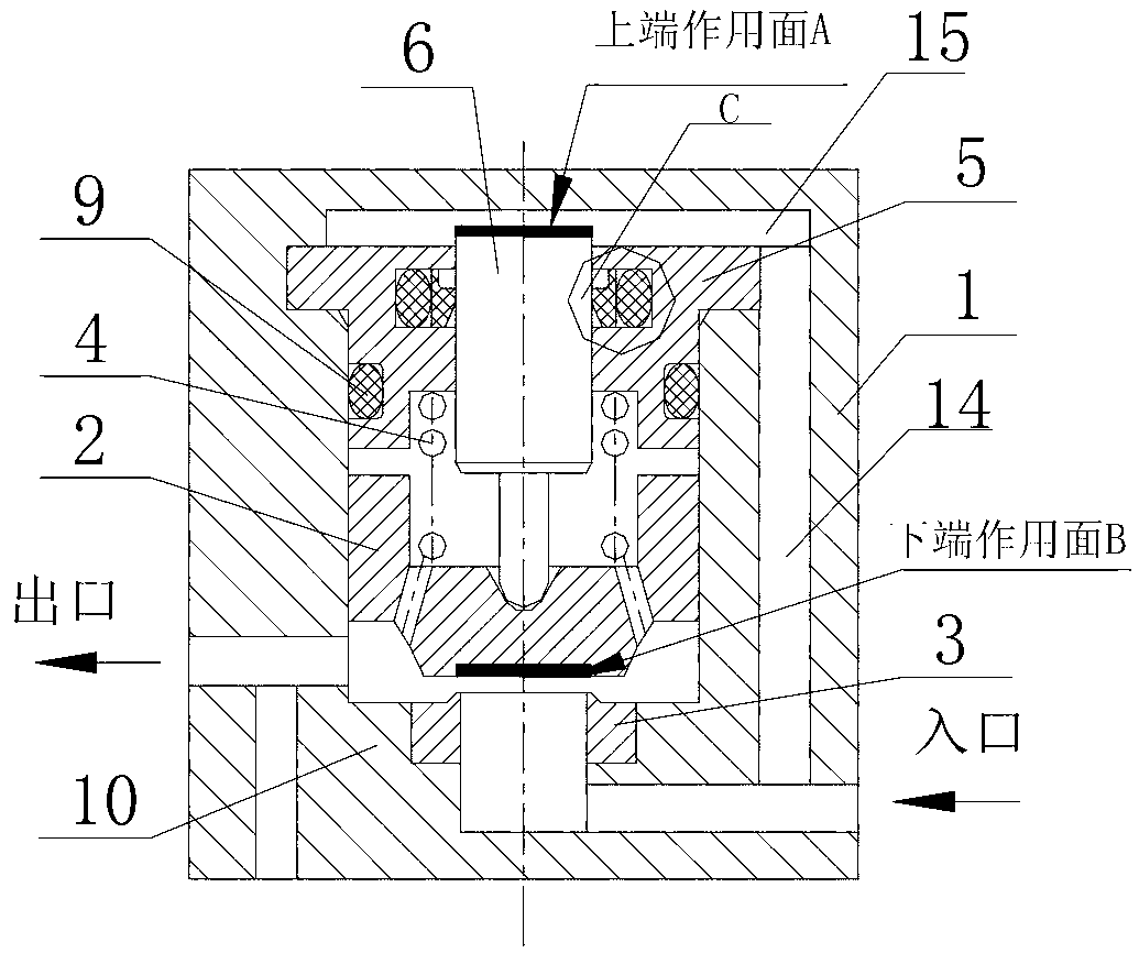
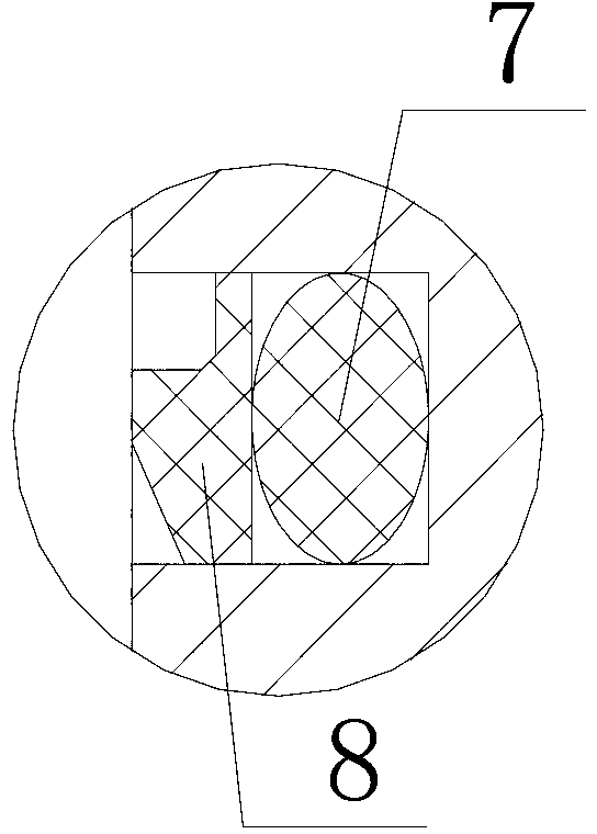
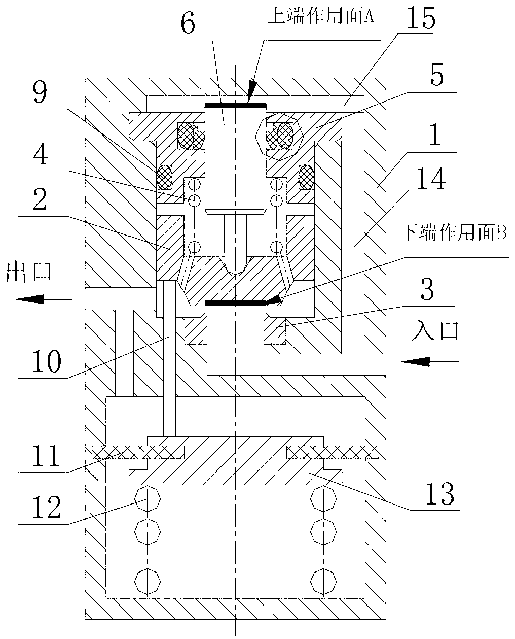
[0021] Such as figure 1 with figure 2 As shown, it is a positive low-friction unloading device for a pressure reducing valve of the present invention, which is the basic form of the present invention. It consists of a valve body 1, a valve core 2, a valve seat 3, an auxiliary spring 4, and an unloading ring 5 , Unloading rod 6, rubber O-ring 7, trapezoidal sealing ring 8, rubber O-ring 9 components.

[0022] The unloading ring is fixedly installed in the valve body and is located between the valve body and the valve core. A cavity 15 is arranged between the unloading ring 5 and the valve body 1. The unloading rod 6 is installed in the unloading ring 5 and the unloading rod 6 The upper end surface of the valve is located in the cavity 15, the lower end surface of the unloading rod 6 is in contact with the valve core 2, and the area of ​​the lower end surface of the valve core 2 is equal to the area of ​​the upper end surface of the unloading rod (that is, the upper end surfac...


PUM


Abstract

The invention relates to a forward low-friction unloading gear for a reducing valve. The forward low-friction unloading gear comprises an unloading ring, an unloading pole, an inlet pressure unloading flow passage and a seal assembly, wherein the unloading ring is fixedly arranged in a valve body and between the valve body and a valve core, a cavity is arranged between the unloading ring and the valve body, the unloading pole is arranged in the unloading ring in a sliding and matched way, the upper end face of the unloading pole is arranged in the cavity, the lower end face of the unloading pole is in contact with the valve core, the areas of the lower end face of the valve core and the upper end face of the unloading pole are equal, assistant springs are arranged between the unloading ring and the valve core, the inlet pressure unloading flow passage is arranged inside the valve body, one end of the inlet pressure unloading flow passage is communicated with an inlet, and the other end of the inlet pressure unloading flow passage is communicated with the cavity. The invention provides the unloading gear capable of enhancing the outlet pressure regulation precision of the reducing valve. The unloading gear disclosed by the invention has the advantages of simple structure, small frictional resistance, convenience in processing and manufacturing, and the like; and the unloading gear is capable of eliminating the influence to the regulation precision of the reducing valve, brought by the inlet pressure change and improving the outlet pressure regulation precision of the reducing valve.

Description

technical field [0001] The invention relates to a positive low-friction unloading device for a pressure reducing valve and a pressure reducing valve, which can be used as an inlet pressure unloading device for a high pressure pressure reducing valve of an engine and a ground test system, and can effectively eliminate the impact of the drop in inlet pressure on the outlet pressure of the pressure reducing valve The effect of adjustment accuracy. Background technique [0002] In the development of final attitude control engine, in order to improve the precision, the thrust device of the engine is required to have a high-precision thrust output. As a system pressure regulating device, the pressure reducing valve needs to improve its outlet pressure regulation accuracy. When the engine is working, the inlet pressure decreases continuously with the gas consumption. The existing direct-acting pressure reducing valve is affected by the inlet pressure change, and the outlet pressur...

Claims


Application Information

Patent Timeline
Patent Type & Authority Applications(China)
IPC IPC(8): F16K47/00F16K17/30
Inventor 罗大亮王春民曾维亮袁洪滨孙亮宋会玲
Owner NO 11 INST OF NO 6 ACADEMY OF CHINA AEROSPACE SCI & TECH
Learn More