A temperature measuring component installed in a flute tube

A flute-shaped tube and component technology, which is applied in the field of temperature measurement components, can solve problems such as welding through, high hot gas velocity, and high probability of defective products, and achieve the effect of avoiding welding connections

Active Publication Date: 2015-10-21
COMAC +1
View PDF6 Cites 0 Cited by
  • Summary
  • Abstract
  • Description
  • Claims
  • Application Information

AI Technical Summary

Problems solved by technology

[0006] However, on the one hand, due to the large variation of the pipe diameter of the pipette, the minimum pipe diameter is about 24-25mm, and the pipe wall of the pipette is relatively thin, about 1mm thick, when the base is welded to the pipette When it is easier to have the problem of weld penetration, the probability of defective products is higher
[0007] On the other hand, due to the high flow rate of hot gas in the flute tube, the thermocouple is usually blown by the hot gas until the probe of the thermocouple sticks to the inner wall of the end of the flute tube, so the actual measured temperature value is not flute-shaped. The temperature of the hot gas at the center of the inside of the tube, but not at the wall of the tube, which is not ideal

Method used


Image

  • A temperature measuring component installed in a flute tube
  • A temperature measuring component installed in a flute tube

Examples


Embodiment Construction

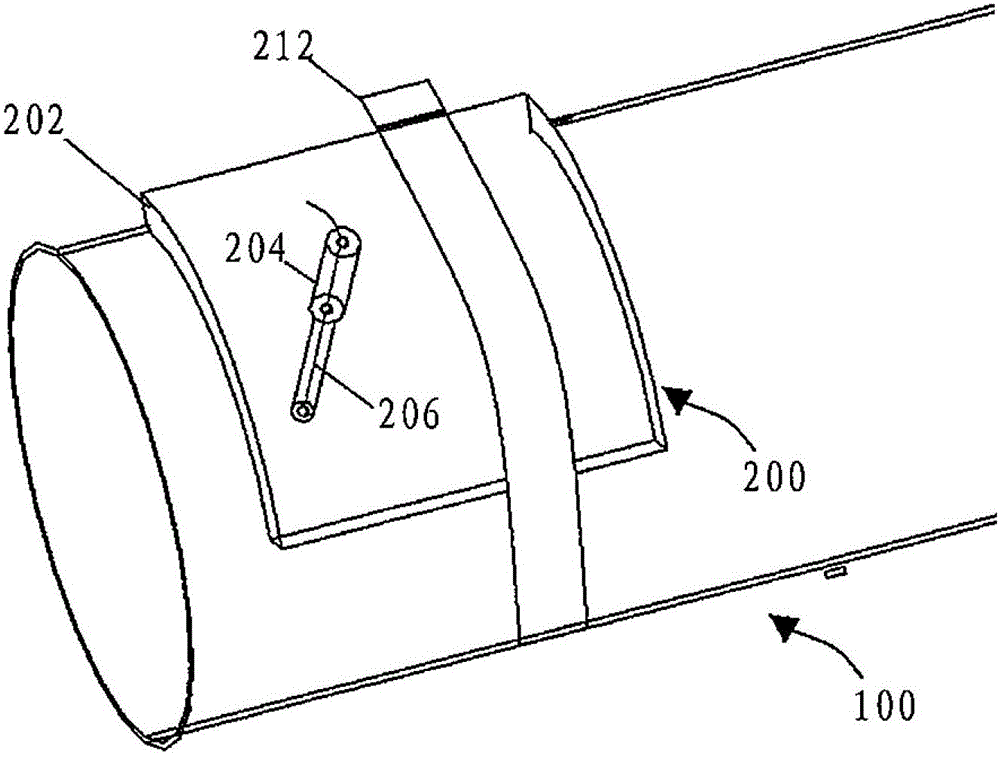
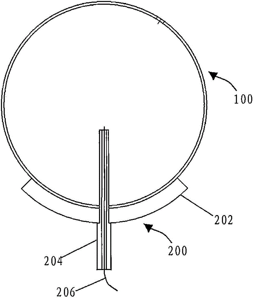
[0025] Such as figure 1 and figure 2 As shown, a temperature measuring assembly 200 installed on a piccolo 100 , wherein the piccolo 100 has a first through hole, the temperature measuring assembly 200 includes a base 202 , a tubular carrier 204 and a thermocouple 206 .

[0026] Specifically, the base 202 is a thin plate-shaped part made of aluminum material, which has a joint surface adapted to the outer surface of the piccolo 100. Specifically, as shown in the figure, the joint surface is arc-shaped and the curvature of the joint surface is the same as The outer surfaces of piccolo 100 have the same curvature. There is also a second through hole on the base 202. When the base 202 is bound to the pictograph 100 by the high temperature resistant tape 212, the joint surface of the base 202 and the outer surface of the pictograph 100 are attached to each other and make the The aforementioned second through hole and the first through hole are aligned with each other. Generall...


PUM

PropertyMeasurementUnit
diameteraaaaaaaaaa
diameteraaaaaaaaaa
diameteraaaaaaaaaa

Abstract

The invention discloses a temperature measuring assembly arranged in a flute pipe. The flute pipe comprises a first through hole, and comprises a base and a tubular bearing piece, wherein the base comprises a joint surface which is matched with an outer surface of the flute pipe; a second through hole is formed in the joint surface; the base is fixed to the flute pipe in a non-welded mode, so that the joint surface is attached to the outer surface of the flute pipe, and the second through hole is aligned with the first through hole; and because the outer diameter reducer of the tubular bearing piece has a boss which can be clamped on the base, a thermocouple is fixed on the tubular bearing piece, and a probe of the thermocouple is exposed from a thin end of the tubular bearing piece, the tubular bearing piece is fixed in the second through hole and the first through hole, and the probe of the thermocouple is approximately positioned in the center of the flute pipe. The thermocouple is born by the tubular bearing piece, so that the probe of the thermocouple can be prevented from being attached to the pipe wall due to the high-flow velocity hot-gas impact in the flute pipe; and therefore, the hot-gas temperature at the central position in the flute pipe can be accurately measured.

Description

technical field [0001] The invention relates to a temperature measuring assembly installed on a flute tube. Background technique [0002] The wing hot air anti-icing system of civil aircraft provides safety guarantee for the aircraft to fly under icing weather conditions, and provides sufficient heat source for the wing, which is the key component of the aircraft to generate lift, to avoid icing on the surface of the wing and affecting the aerodynamic shape of the wing . [0003] After the design of the wing hot gas anti-icing system is completed, a series of calculation analysis, test flight, etc. are required to verify whether the system design meets the design requirements and airworthiness provisions. As an important verification method, flight test has been paid more and more attention. [0004] According to the performance verification of the wing hot gas anti-icing system and the compliance verification requirements of CCAR25. Design requirements and clause complia...

Claims


Application Information

Patent Timeline
Patent Type & Authority Patents(China)
IPC IPC(8): G01K7/02G01K1/14G01K13/024
Inventor 霍西恒王大伟李革萍汤国伟
Owner COMAC
Why Eureka
Try Eureka