
Focal point positioning device for astronomical telescope

An astronomical telescope and positioning device technology, applied in telescopes, installation, optics and other directions, can solve the problems of poor measurement accuracy, drop, inaccurate positioning and detection performance, etc., and achieve the effects of easy installation and carrying, simple use, and easy fixing and operation.

Inactive Publication Date: 2013-04-03
OCEANOGRAPHIC INSTR RES INST SHANDONG ACAD OF SCI
View PDF4 Cites 11 Cited by
  • Summary
  • Abstract
  • Description
  • Claims
  • Application Information

AI Technical Summary

Problems solved by technology

[0005] The purpose of the present invention is to provide a device for focus positioning of astronomical telescopes, which can quickly and conveniently locate the focus of the telescope accurately, and solve the problems of decreased detection performance and poor measurement accuracy caused by inaccurate focus positioning of the laser radar receiving telescope.

Method used


Image

  • Focal point positioning device for astronomical telescope
  • Focal point positioning device for astronomical telescope
  • Focal point positioning device for astronomical telescope

Examples


Embodiment Construction

[0029] In order to make the objectives, technical solutions and advantages of the embodiments of the present invention clearer, the specific embodiments of the present invention will be described in further detail below with reference to the accompanying drawings.

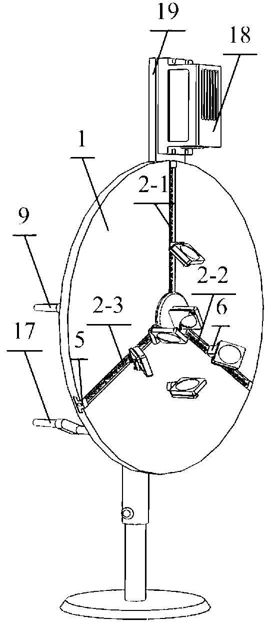
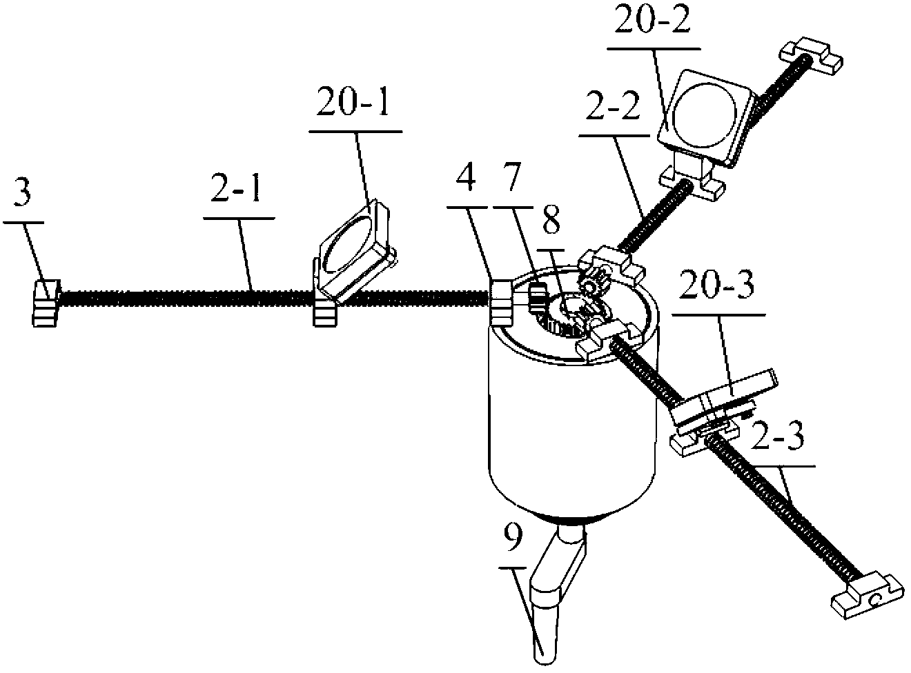
[0030] like Figure 1-Figure 3 As shown, the device for locating the focus of the telescope provided by the present invention includes a mechanical structure: a bearing platform 1, a screw rod 2 (2-1 to 2-3), an outer screw rod positioning seat 3, a screw rod inner positioning seat 4, Bearing 5, sliding seat 6, driven bevel 7, active bevel 8, sliding rocker 9, sliding rocker bearing 10, bearing spacer 11, large synchronous pulley 12, small synchronous pulley 13, synchronous belt 14, Turntable support 15 , turntable bearing 16 , turntable crank 17 , turntable crank bearing 23 .

[0031] like image 3 , Figure 4 As shown, the device for locating the focus of a telescope provided by the present invention includes ...


PUM


Abstract

The invention relates to a focal point positioning device for an astronomical telescope. The focal point positioning device for the astronomical telescope comprises a bearing platform, spectroscope lenses, reflector lenses and three screw rods, wherein the bearing platforms can be rotated around a shaft; the spectroscope lenses are arranged above the shaft; the reflector lenses are arranged on the bearing platform; the three screw rods are arranged on the bearing platform and are distributed at angles of 120 DEG mutually; the screw rods and the reflector lenses are positioned on the same linear optical path and are distributed on both sides of the spectroscope lenses respectively; sliding seats which can be moved back and forth along the screw rods are sleeved on the screw rods; and the spectroscope lenses and the reflector lenses are arranged on the sliding seats respectively through adjustable lens bases. The focal point positioning device is convenient to assemble and carry, focusing light sources can be selected according to the wavelength of detection signals of a laser radar, optical paths are finely tuned by the two-dimensional adjustable lens bases, and the spatial distribution of three beams of parallel light is adjusted through an operating crank of the sliding seat and an operating crank of a turntable, so that the three beams of parallel light enters an objective lens of the astronomical telescope to be focused, focus points are rapidly and accurately positioned, and the focal point positioning device is easy to use, low in cost and is convenient to fix and operate.

Description

technical field [0001] The invention belongs to the field of laser radar, and in particular relates to a focus positioning device for an astronomical telescope, that is, a device for accurate, simple and fast positioning of the focus of a telescope in an atmospheric detection laser radar receiving system and a method for using the same. Background technique [0002] With the rapid development of laser technology and photoelectric detection technology, atmospheric detection lidar has become an effective means of atmospheric parameter measurement, and is a powerful tool for real-time monitoring of atmospheric wind field, temperature, aerosol, cloud, water vapor and pollutants. Significant advantages such as accuracy, high sensitivity and high spatiotemporal resolution. [0003] The accurate positioning of the telescope focus in the lidar receiving system is one of the key technologies to ensure the effective detection of atmospheric lidar, which is related to the accurate desi...

Claims


Application Information

Patent Timeline
Patent Type & Authority Applications(China)
IPC IPC(8): G01S7/48G01S7/481G02B7/00G02B7/198G02B23/00
Inventor 王章军陈超曲君乐杜立彬李先欣吕斌杨倩吴承璇刘杰王秀芬李正宝张浩
Owner OCEANOGRAPHIC INSTR RES INST SHANDONG ACAD OF SCI
Learn More