
Blue-phase liquid crystal display device

A blue-phase liquid crystal and display technology, used in instruments, nonlinear optics, optics, etc., can solve the problems of low driving voltage, increased driving electrode structure, low light transmittance, etc., to reduce production, improve aperture ratio, increase The effect of light transmittance

Inactive Publication Date: 2013-04-03
HEBEI UNIV OF TECH
View PDF6 Cites 20 Cited by
  • Summary
  • Abstract
  • Description
  • Claims
  • Application Information

AI Technical Summary

Problems solved by technology

[0003] The pixel electrode with slits and the common electrode are arranged under the pixel electrode to form the light transmission above the electrode and the storage capacitor under the pixel electrode, which increases the light transmission area and improves the light transmittance, but the driving voltage is lower than that of the pixel electrode. The driving electrode structure of conventional coplanar switching increases the
In order to reduce the driving voltage, it has been proposed to use protrusions and raised electrode structures to reduce the driving voltage, and by optimizing the shape of the protrusions, a higher transmittance and a lower driving voltage have been obtained, but because the entire pixel It is still necessary to make an additional storage capacitor to maintain the voltage, so the overall light transmittance is not high

Method used


Image

  • Blue-phase liquid crystal display device
  • Blue-phase liquid crystal display device
  • Blue-phase liquid crystal display device

Examples


Embodiment 1

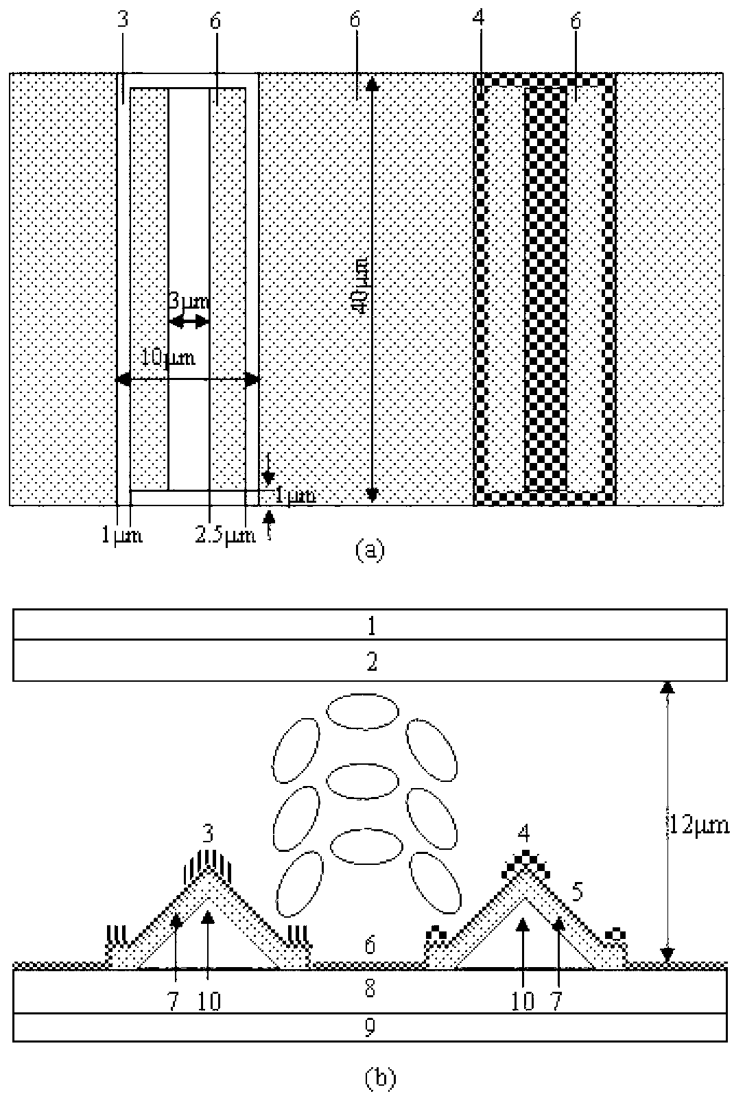
[0030] Such as figure 1 As shown (where (a) is a top view of the surface of the lower substrate, and (b) is a cross-sectional view), the structure of the blue-phase liquid crystal display device of this embodiment includes: an upper polarizer 1, an upper substrate 2, a blue-phase liquid crystal (BPLC) , the first Pixel electrode 3, the second Pixel electrode 4, the slit 5, the insulating layer 6, the Common electrode 7, the lower substrate 8, the lower polarizer 9 and the triangular protrusion 10,

[0031] in:

[0032] The lower surface of the upper middle and upper polarizer 1 is connected to the upper surface of the upper substrate 2, the upper surface of the lower middle and lower polarizer 9 is connected to the lower surface of the lower substrate 8, and other components are between the upper substrate 2 and the lower substrate 8, wherein Protrusions 10 are uniformly distributed on the upper surface of the lower substrate 8, the Common electrode 7 covers the protrusions 1...

Embodiment 2

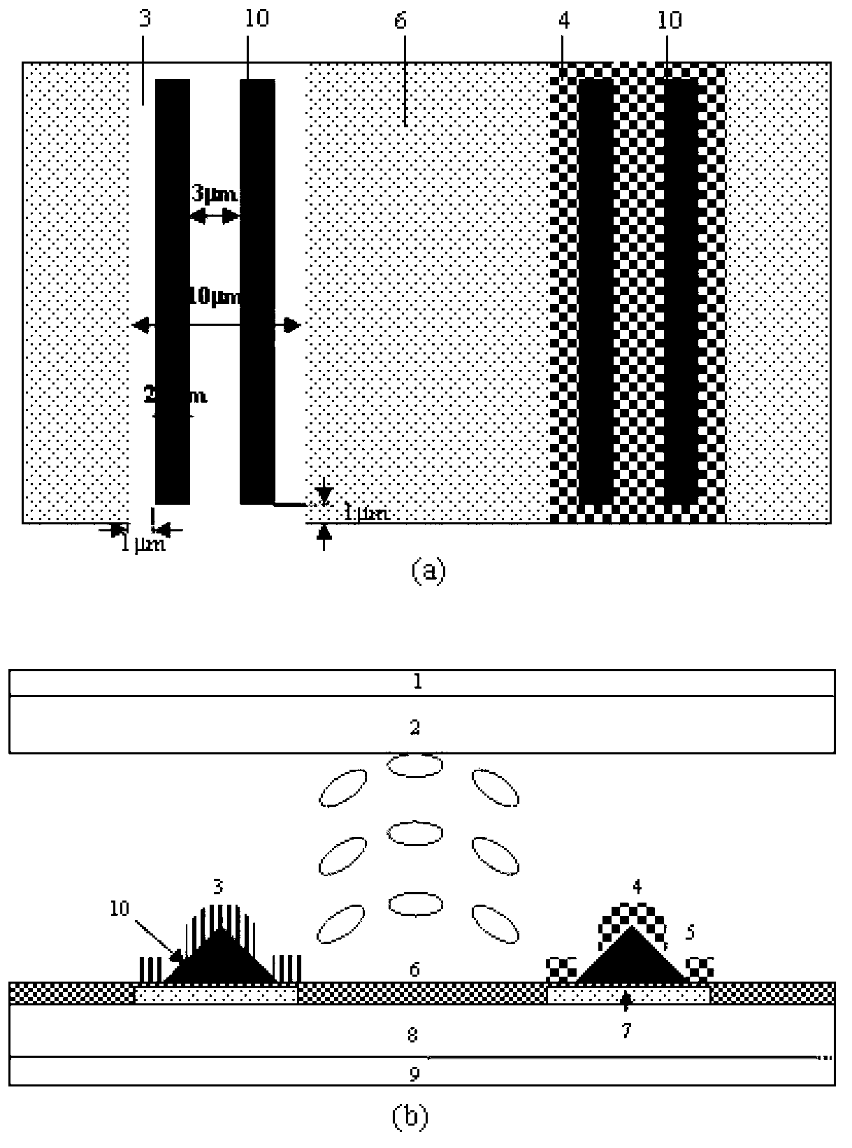
[0045] Such as image 3 As shown (where (a) is a top view of the surface of the lower substrate, and (b) is a cross-sectional view), the structure of the blue-phase liquid crystal display device of this embodiment includes: an upper polarizer 1, an upper substrate 2, a blue-phase liquid crystal (BPLC) , the first Pixel electrode 3, the second Pixel electrode 4, the slit 5, the insulating layer 6, the Common electrode 7, the lower substrate 8, the lower polarizer 9 and the triangular protrusion 10,

[0046] in:

[0047] The lower surface of the upper middle and upper polarizer 1 is connected to the upper surface of the upper substrate 2, the upper surface of the lower middle and lower polarizer 9 is connected to the lower surface of the lower substrate 8, and other components are between the upper substrate 2 and the lower substrate 8, wherein Strip-shaped Common electrodes 7 are made on the upper surface of the lower substrate 8, arranged at equal intervals, covered with an i...

Embodiment 3

[0060] Such as Figure 5 As shown (where (a) is a top view of the surface of the lower substrate, and (b) is a cross-sectional view), the structure of the blue-phase liquid crystal display device of this embodiment includes: an upper polarizer 1, an upper substrate 2, a blue-phase liquid crystal (BPLC) , a first Pixel electrode 3, a second Pixel electrode 4, a slit 5, an insulating layer 6, a Common electrode 7, a lower substrate 8, a lower polarizer 9 and a trapezoidal protrusion 10,

[0061] in:

[0062] The lower surface of the upper middle and upper polarizer 1 is connected to the upper surface of the upper substrate 2, the upper surface of the lower middle and lower polarizer 9 is connected to the lower surface of the lower substrate 8, and other components are between the upper substrate 2 and the lower substrate 8, wherein Strip-shaped Common electrodes 7 are made on the upper surface of the lower substrate 8, arranged at equal intervals, covered with an insulating lay...


PUM

PropertyMeasurementUnit
Widthaaaaaaaaaa
Widthaaaaaaaaaa
Thicknessaaaaaaaaaa

Abstract

The invention relates to a blue-phase liquid crystal display device. The blue-phase liquid crystal display device structurally comprises an upper polaroid, an upper substrate, a middle part, a lower substrate and a lower polaroid; the lower polaroid, the lower substrate, the middle part, the upper substrate and the upper polaroid are sequentially arranged from bottom to top according to an incident light passing sequence; and the middle part consists of blue-phase liquid crystals (BPLC), a first Pixel electrode, a second Pixel electrode, a fine gap, an insulating layer, a Common electrode and a bulge. According to the invention, by introducing the fine gap structure and the bottom surface Common electrode and through an edge field formed by the Pixel electrodes and the Common electrode, the light transmissivities of the upper parts of the electrodes are effectively improved, so that the light utilization rate of a blue-phase liquid crystal display is effectively improved. Meanwhile, the Pixel electrodes and the Common electrode below the Pixel electrodes can be used as storage capacitances, so that separate manufacturing of the storage capacitances is reduced and the actual aperture ratio (the light transmittance area) of the blue-phase liquid crystal display is improved.

Description

technical field [0001] The invention designs a device in the technical field of liquid crystal display, in particular a device for increasing the transmittance of a blue-phase liquid crystal (BPLC) display. Background technique [0002] The blue phase liquid crystal display has the characteristics of response time below milliseconds, wide viewing angle and high contrast ratio, and does not require an alignment layer in the production process, nor does it need to impose strict restrictions on the thickness of the liquid crystal layer, the production cost is low, and the manufacturing process is simpler. , which is considered to have the most potential to become the next generation of liquid crystal displays. The traditional blue-phase liquid crystal display is driven in the form of the driving electrodes of the coplanar switching liquid crystal display. It is necessary to make a storage capacitor to obtain a high voltage retention rate, because only a small amount of light pa...

Claims


Application Information

Patent Timeline
IPC IPC(8): G02F1/1343G02F1/137
Inventor 孙玉宝栗鹏
Owner HEBEI UNIV OF TECH
Learn More