
Head and neck CTA (computed tomography angiography) image layering method and device

A head and neck, imaging technology, applied in the medical field, can solve the problems of low blood vessel separation efficiency, head and neck CTA image processing, etc.

Active Publication Date: 2013-04-03
NEUSOFT CORP
View PDF4 Cites 7 Cited by
  • Summary
  • Abstract
  • Description
  • Claims
  • Application Information

AI Technical Summary

Problems solved by technology

[0004] In the prior art, hospitals usually use manual methods to separate blood vessels in head and neck CTA images. First, select the area containing a large number of bone tissues and blood vessels in the head and neck CTA images, and then manually mark the outline of blood vessels. Each layer of image All need to be processed, and finally the image of blood vessels can be generated in the CTA image. This method does not perform any processing on the head and neck CTA image in advance, but directly separates the blood vessels, and finally makes the head and neck CTA image The separation efficiency of blood vessels in the image is very low

Method used


Image

  • Head and neck CTA (computed tomography angiography) image layering method and device
  • Head and neck CTA (computed tomography angiography) image layering method and device
  • Head and neck CTA (computed tomography angiography) image layering method and device

Examples


Embodiment 1

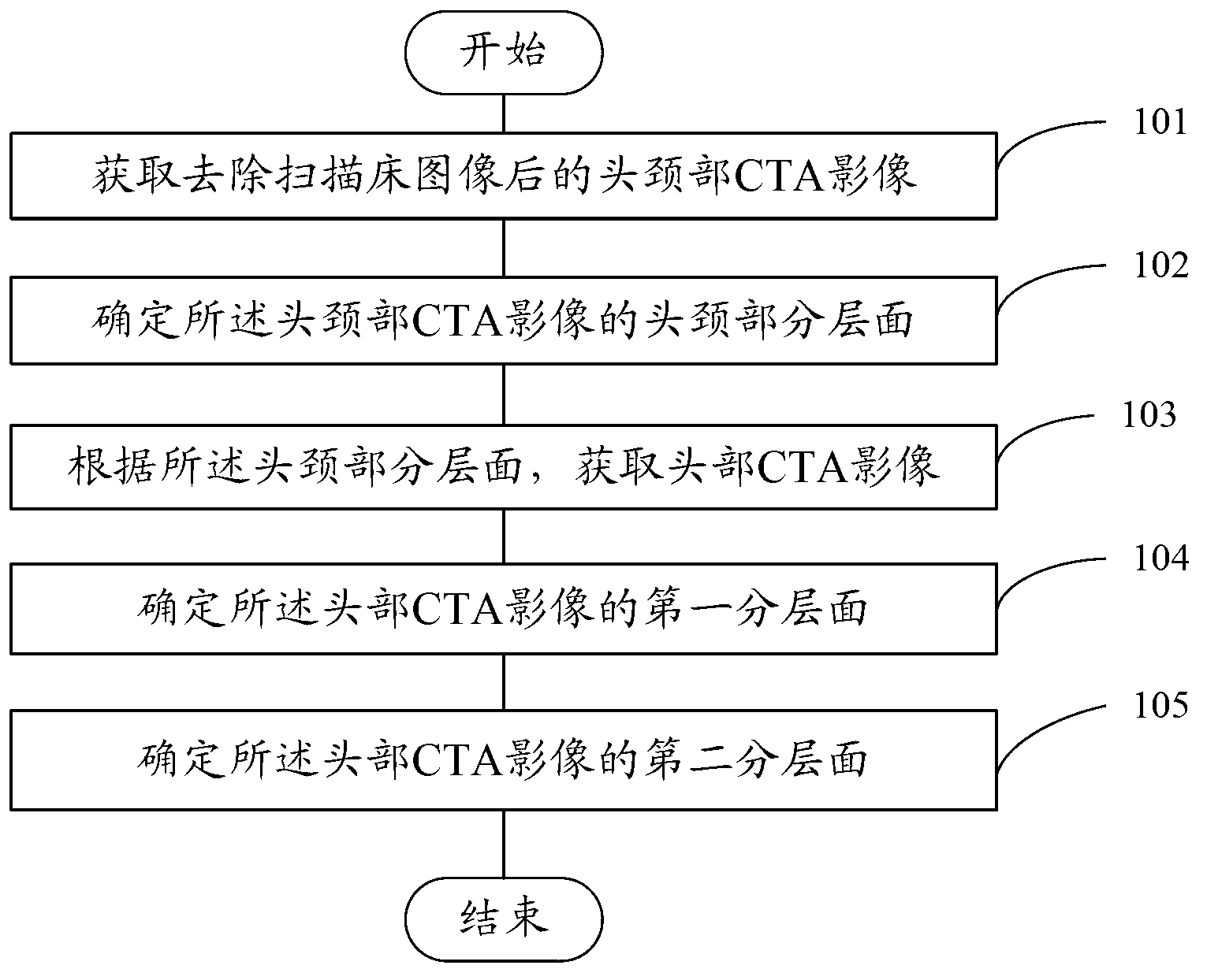
[0078] refer to figure 1 , figure 1 It is a flow chart of Embodiment 1 of a method for stratifying head and neck CTA images provided by the present invention. This embodiment may specifically include:

[0079] Step 101. Acquire the head and neck CTA image after removing the scanning bed image.

[0080] In this embodiment, the CTA image of the head and neck is acquired firstly, and secondly, the scanned bed image is removed from the acquired CTA image of the head and neck. Removing the scanning bed image of the head and neck CTA image is a preprocessing step of the head and neck CTA image in this embodiment.

[0081] In actual operation, the scanning bed image of head and neck CTA images can be removed by the region growing method of automatic selection of seed points. Specifically, the method for removing the scanning bed image of the head and neck CTA image is a prior art, and the method used to remove the scanning bed image of the head and neck CTA image does not affect t...

Embodiment 2

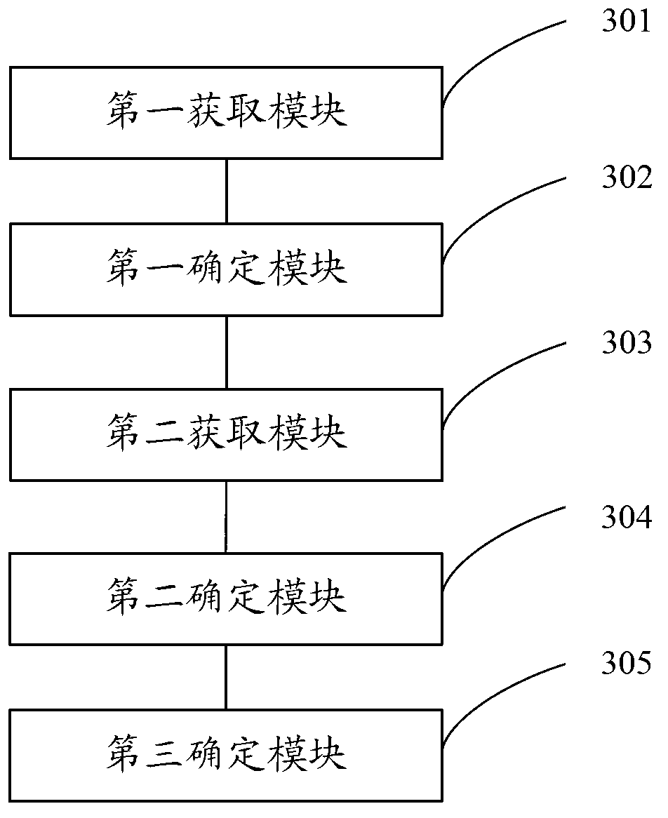
[0110] refer to image 3 , image 3 It is a structural diagram of Embodiment 2 of a head and neck CTA image layering device provided by the present invention. This embodiment may specifically include:

[0111] The first obtaining module 301 is configured to obtain the head and neck CTA image after removing the scanning table image.

[0112] The first determining module 302 is configured to determine the slices of the head and neck part of the head and neck CTA image.

[0113] refer to Figure 4 , Figure 4 It is a structural diagram of the first determination module 302, and the first determination module 302 includes:

[0114] The first acquisition sub-module 401 is configured to acquire the initial profile of the head and neck CTA image.

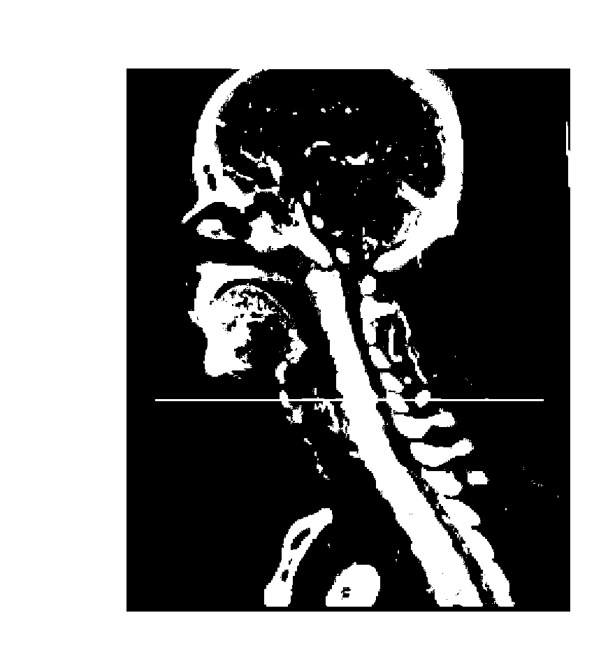
[0115] The second obtaining sub-module 402 is configured to obtain the processed side profile after binarizing the initial side profile.

[0116] The first determination sub-module 403 is configured to determine the partial slices of...


PUM


Abstract

An embodiment of the invention discloses head and neck CTA (computed tomography angiography) image layering method and device. The method includes: acquiring a head and neck CTA image with a scanning table image removed; determining a head and neck partition of the head and neck CTA image; acquiring a head CTA image according to the head and neck partition; determining a first partition of the head CTA image, and determining a second partition of the head CTA image. Before vessel separation, the head and neck CTA image are layered in advance according to the structural features of head and neck, and accordingly efficiency of separating vessels in the head and neck CTA image is improved.

Description

technical field [0001] The invention relates to the field of medicine, in particular to a method and device for stratifying head and neck CTA images. Background technique [0002] CTA, that is, CT angiography, is also called non-invasive angiography in medicine, and CTA images are vascular images formed by CTA technology. [0003] At present, because CTA technology has high sensitivity and specificity for the diagnosis of intracranial aneurysms, and is non-invasive, compared with traditional technology, it also greatly reduces the pain of the examinee. In the CTA images of the head and neck, doctors can detect diseases such as arteriosclerosis and vascular microaneurysms based on the separated blood vessels. [0004] In the prior art, hospitals usually use manual methods to separate blood vessels in head and neck CTA images. First, select the area containing a large number of bone tissues and blood vessels in the head and neck CTA images, and then manually mark the outline ...

Claims


Application Information

Patent Timeline
Patent Type & Authority Applications(China)
IPC IPC(8): G06T7/00A61B6/03
Inventor 赵大哲覃文军杨金柱宫照煊袁玉亮耿欢
Owner NEUSOFT CORP
Learn More