
Vascular remodeling method based on parameter deformation model energy optimization

A deformation model and energy optimization technology, applied in the field of diagnosis and treatment of clinical vascular diseases, can solve the problems of low accuracy of vascular centerline, loss of spatial three-dimensional information, and influence on reconstruction accuracy, etc., to achieve increased accuracy, wide applicability, The effect of high reconstruction accuracy

Active Publication Date: 2013-04-03
BEIJING INSTITUTE OF TECHNOLOGYGY
View PDF1 Cites 7 Cited by
  • Summary
  • Abstract
  • Description
  • Claims
  • Application Information

AI Technical Summary

Problems solved by technology

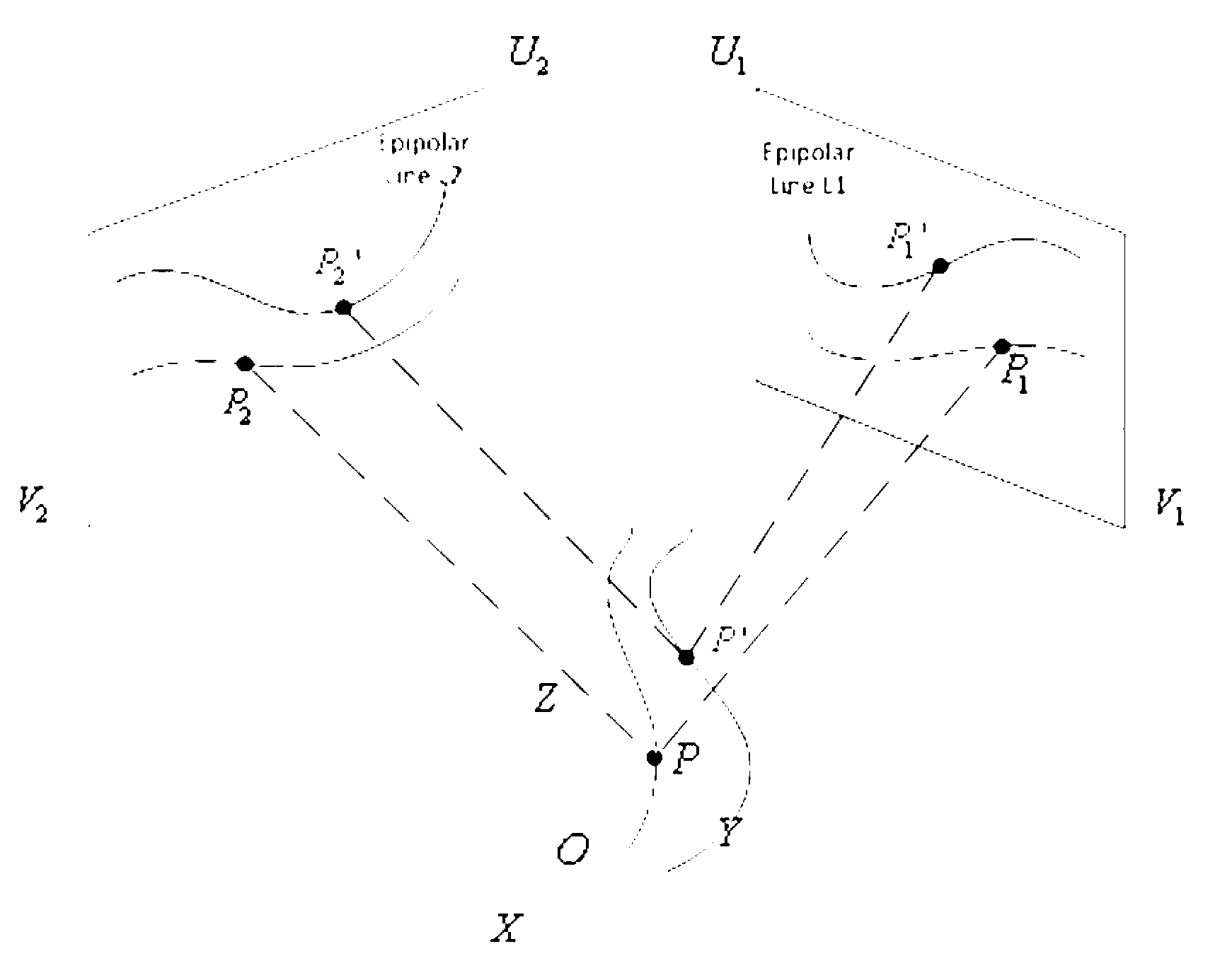
[0007] 1. Use the epipolar constraint method to find the corresponding point pairs in the two contrast images, but because of the system error and vessel translation, there is a large error in the point pairs obtained by the epipolar constraint, which affects the reconstruction accuracy
[0008] 2. The parametric deformation model is used to iteratively approximate the real vascular centerline, but the original corresponding point pairs in the two angiographic images are not strictly corresponding after moving under the action of internal and external forces, so the accuracy of the reconstructed vascular centerline Low
However, due to the X-ray perspective projection imaging, a large amount of spatial three-dimensional information is lost in the imaging process, and doctors usually can only judge lesions based on a few two-dimensional projection images, so the subjectivity is strong
The clinical diagnosis process often requires doctors to have strong professional knowledge and a lot of operating experience

Method used


Image

  • Vascular remodeling method based on parameter deformation model energy optimization
  • Vascular remodeling method based on parameter deformation model energy optimization
  • Vascular remodeling method based on parameter deformation model energy optimization

Examples


Embodiment Construction

[0031] The advantages and spirit of the present invention can be further understood through the following detailed description of the invention and the accompanying drawings.

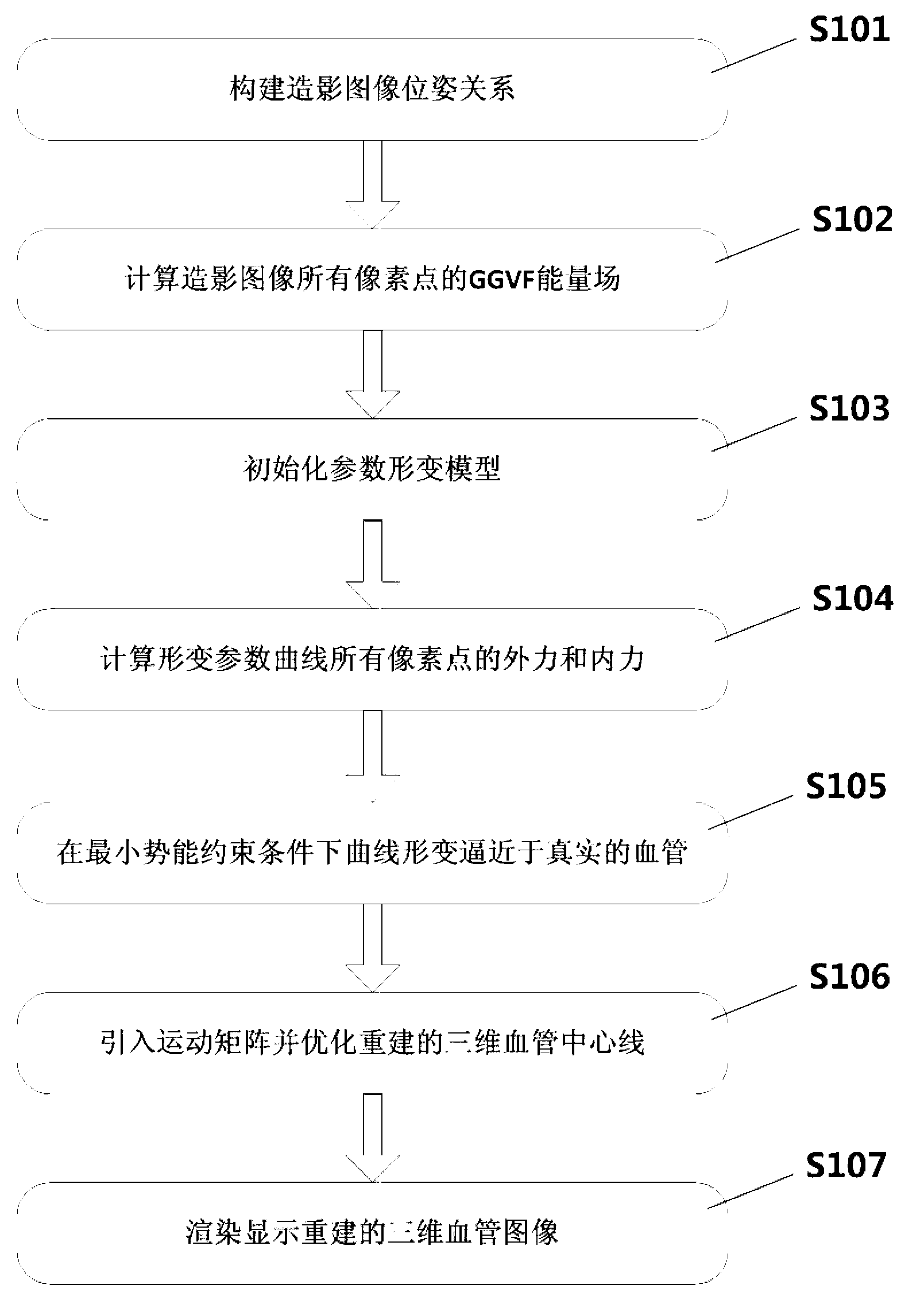
[0032] attached figure 1 To reconstruct the flowchart, the three-dimensional reconstruction of blood vessels includes the following steps:

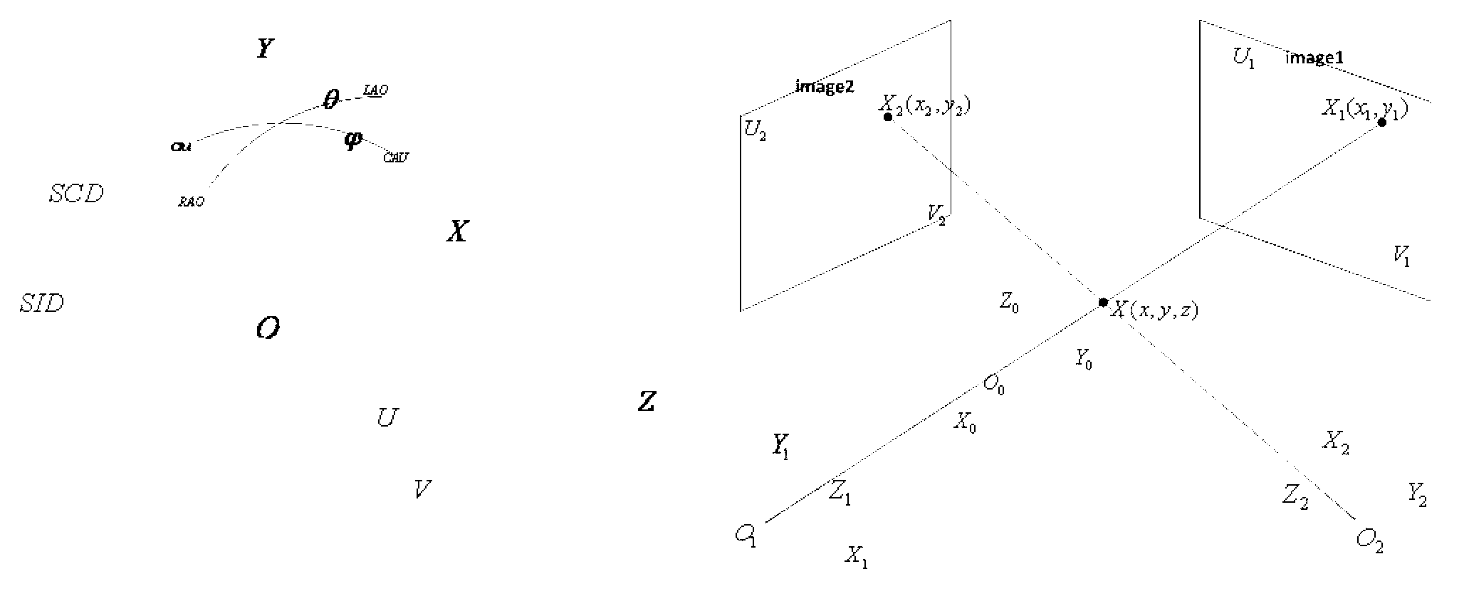
[0033] Step S101, according to the system information of the two contrast images, including left and right rotation angles (LAO, RAO), head-foot rotation (CRAN, CAUD), radial translation (SID), and calculate the rotation between the two contrast images Translate the relative matrix. A point X on the centerline of the blood vessel in three-dimensional space i (x i ,y i ,z i ) is projected onto the image plane of the imaging equipment as X 1,i =(x 1,i ,y 1i ) T ,(x 1,c ,y 1,c ) T The coordinates of the principal point.

[0034]

[0035]

[0036] Step S102, for the two read-in contrast images, calculate the GGVF energy field vector of each pixel in ...


PUM


Abstract

The invention provides a vascular remodeling method based on parameter deformation model energy optimization. A convenient tool is provided for directed treatment of vascular diseases. The method comprises the following steps of: 1. establishing a parameter deformation model; 2. performing generalized gradient vector current (GGVF) space back projection synthesis, namely performing back projection synthesis on a GGVF energy field vector in two contrastographic pictures in a three-dimensional space according to an adaptive weighting coefficient, and taking the synthesized vector as an external force field of the parameter deformation model; 3. performing parameter deformation curve iterative approximation, namely allowing the deformation curve to continuously and iteratively approximate to a real vascular center line due to the action of the external force and self-elasticity bending internal force of the GGVF synthesis model, and obtaining the result with minimum energy under the constraint conditions with minimum distance potential energy; 4. introducing a motion estimation matrix to represent the relative displacement of blood vessels in two contrastographic pictures due to the breathing movement and heartbeat; and 5. optimizing the reconstruction result.

Description

technical field [0001] The invention relates to a blood vessel reconstruction method based on parameter deformation model energy optimization, which is suitable for diagnosis and treatment of clinical blood vessel diseases. Background technique [0002] The principle of coronary angiography imaging is: coronary angiography (Coronary Angiography, CAG) refers to the selective insertion of catheters to the left and right coronary artery openings after percutaneous arterial puncture and injection of contrast agent, so as to display the anatomical structure of the coronary arteries and a method of cardiovascular angiography of lesions. Coronary angiography is usually referred to simply as coronary angiography. The specific operation method is: a cardiac catheter is sent from the femoral artery at the root of the patient's thigh or the elbow artery of the upper arm, and under the guidance of X-ray angiography (XRA) images The tip of the catheter is sent all the way to the aortic ...

Claims


Application Information

Patent Timeline
IPC IPC(8): G06T17/00
Inventor 杨健刘越王涌天丛伟建
Owner BEIJING INSTITUTE OF TECHNOLOGYGY
Learn More