

Novel communication-in-motion low-profile planar antenna system
A flat-panel antenna, moving-in-the-move technology, applied in antennas, antenna arrays, electrical components, etc., can solve the problems of slow star capture, large size, and high height, so as to improve reception efficiency, ensure accuracy, and reduce costs. Effect
- Summary
- Abstract
- Description
- Claims
- Application Information
AI Technical Summary
Problems solved by technology
Method used
Image

Examples
Embodiment Construction
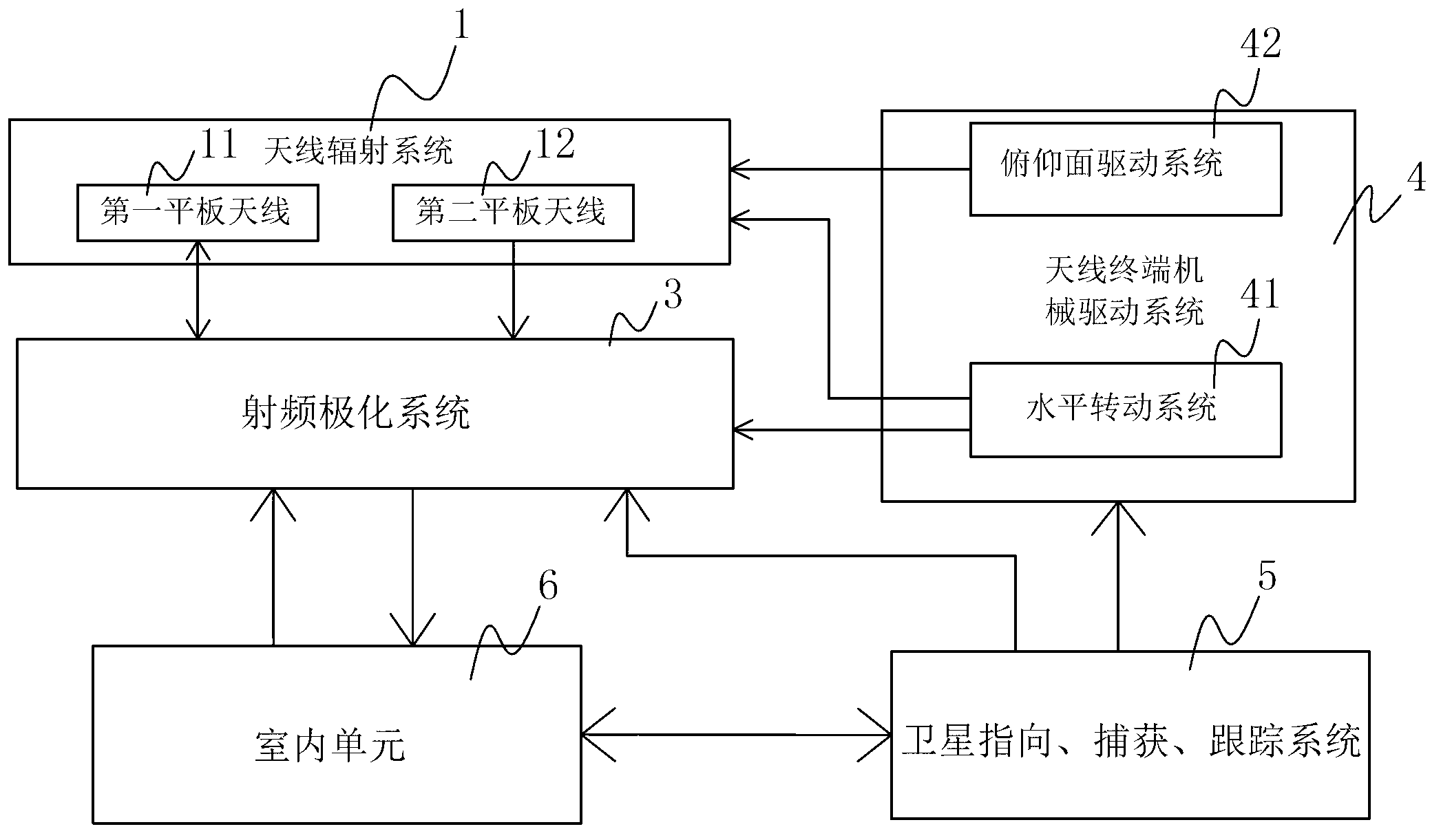
[0045] refer to figure 1 As shown, a new type of "communication in motion" low-profile panel antenna system of the present invention is a dual-array receiving / transmitting antenna system that realizes "communication in motion" on the Ku band, and is mainly composed of the following subsystems, refer to figure 1 As shown, it includes antenna radiation system 1 , radio frequency polarization system 3 , antenna terminal mechanical drive system 4 , satellite pointing, acquisition and tracking system 5 and indoor unit 6 . The antenna radiation system 1 is connected to the radio frequency polarization system 3, and the radio frequency polarization system 3 receives or sends satellite radiation signals through the antenna radiation system 1, and the antenna radiation system 1 and the radio frequency polarization system 3 are installed on the antenna terminal mechanical drive system 4 The antenna terminal mechanical driving system 4 is used to drive the antenna radiation system 1 to ...
PUM
 Abstract
Description
Claims
Application Information