

Display screen back plate and display screen with same
A display screen and back panel technology, which is applied to instruments, cabinets/cabinets/drawer parts, optics, etc., can solve problems such as increasing the distance of installation holes, the width of display screens, the shape and strength of installation holes 3, etc. , to achieve the effect of shortening the vertical distance, good visual effect, saving materials and space
- Summary
- Abstract
- Description
- Claims
- Application Information
AI Technical Summary
Problems solved by technology
Method used
Image

Examples
Embodiment Construction
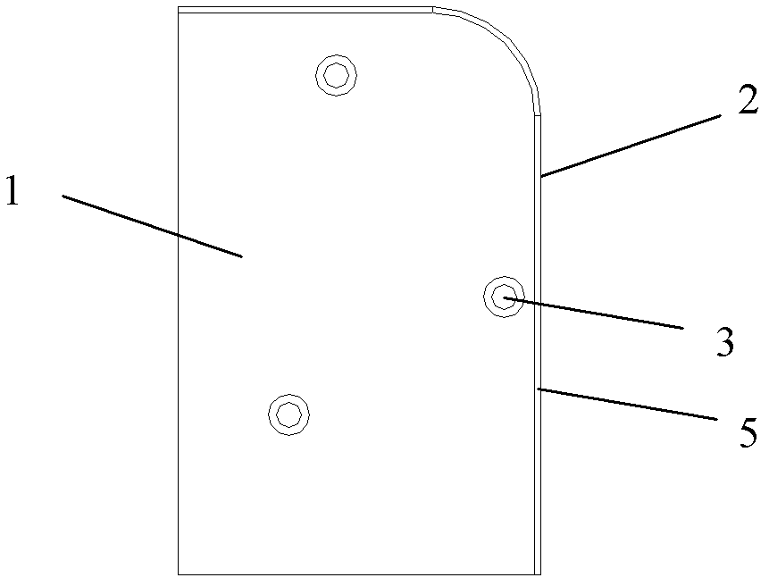
[0013] figure 2 Among them, the back panel of the display screen includes a board body 1 and a folded edge 2. Between the board body 1 and the folded edge 2 is the edge 5 of the board body 1 as a bending place, that is, the folded edge 2 is formed from the edge 5 of the board body 1 to a Side bend. A mounting hole 3 is provided on the board body 1 close to the edge 5 , and the mounting hole 3 is a threaded hole through which screws for mounting and fixing the display screen backboard pass.
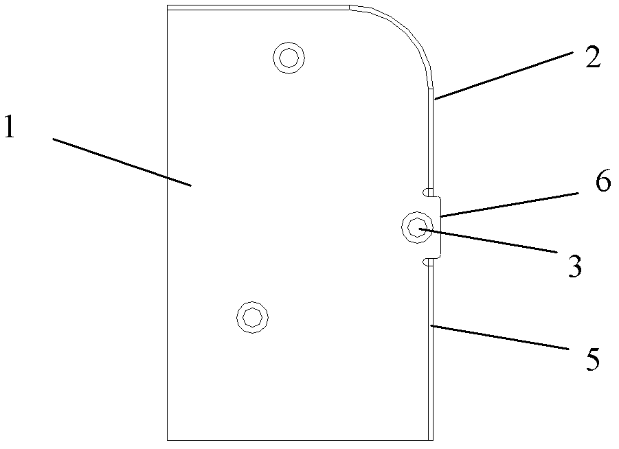
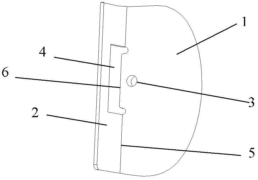
[0014] In addition, a perforated hole 4 is provided on the folded edge 2, such as Figure 3-7 As shown, the perforated hole 4 is elongated and arranged around the installation hole 3, and the top end of the perforated hole 4 in the length direction ( image 3 The left end of the middle hole 4) is set on the edge 5 or extends beyond the edge 5 to the plate body 1.
[0015] Such as image 3 In the shown embodiment one, the broken hole 4 is in a concave shape, and its opening faces the i...
PUM
 Abstract
Description
Claims
Application Information