Combined imaging modalities for radiation treatment planning

A technique for radiation therapy and planning, applied in the fields of delivery of therapeutic radiation to patients and generation of radiation therapy plans, which can solve different problems

Active Publication Date: 2013-04-10
SIEMENS MEDICAL SOLUTIONS USA INC
View PDF4 Cites 4 Cited by
  • Summary
  • Abstract
  • Description
  • Claims
  • Application Information

AI Technical Summary

Problems solved by technology

However, the electron density used for a particular type of tissue will be different for different patients, so the dose calculated in th

Method used


Image

  • Combined imaging modalities for radiation treatment planning
  • Combined imaging modalities for radiation treatment planning
  • Combined imaging modalities for radiation treatment planning

Examples


Embodiment Construction

[0018] The following description is provided to enable any person skilled in the art to make and use the described embodiments and to explain the best mode contemplated for carrying out the described embodiments. Various modifications, however, will still be apparent to those skilled in the art.

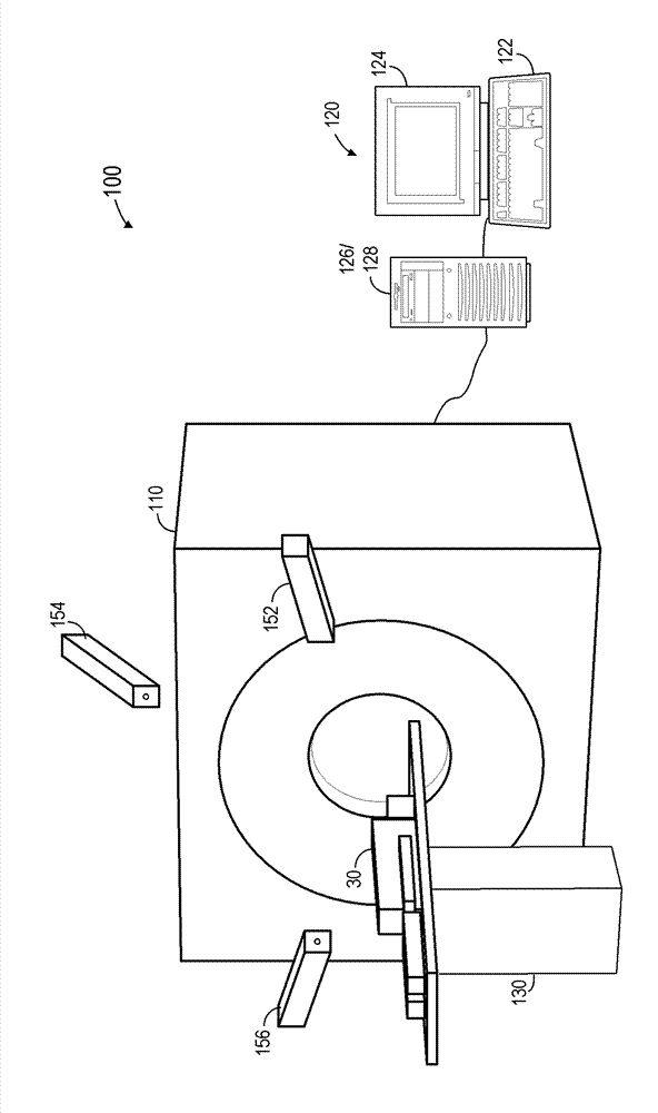
[0019] FIG. 1 illustrates an MRI system 100 for generating images of a patient volume. The MRI system 100 includes an MRI scanner 110 , an operator console 120 and a table 130 . The main components (not shown) of the MRI scanner 110 include the main magnet to polarize the atoms in the patient, the shim coils to correct for inhomogeneities in the magnetic field of the main magnet, to excite the sample and to detect the results. The radio frequency system for the resulting signal and the gradient coils used to localize the resulting signal.

[0020] In operation, and under the control of operator operating console 120 , patient 140 is placed on table 130 and moved into the magnetic f...


PUM


Abstract

The invention discloses combined imaging modalities for radiation treatment planning. A system includes acquisition of a first three-dimensional image of a patient volume using a magnetic resonance imaging scanner (110), acquisition of a second three-dimensional image of the patient volume using cone beam radiation emitted by the linear accelerator (205), and generation of a radiation treatment plan (S450, S460) based on the first image and the second image.

Description

technical field [0001] The embodiments described below generally relate to the delivery of therapeutic radiation to a patient. More specifically, certain embodiments are directed to the generation of radiation therapy plans. Background technique [0002] In conventional radiation therapy, a beam of radiation is directed at a target volume (such as a cancerous tumor) within the patient. The radiation beam delivers a predetermined dose of therapeutic radiation to the target volume according to the established treatment plan. The delivered radiation kills cells in the target volume by causing ionization or other radiation-induced cell damage within the cells. [0003] Treatment plans are designed to deliver a specific dose of radiation to a target volume while ensuring that surrounding healthy tissue does not receive unsafe doses. Treatment planning design thus requires the identification of the various tissues within the patient volume (ie to identify the target, surroundin...

Claims


Application Information

Patent Timeline
IPC IPC(8): A61N5/00
CPCA61N2005/105A61N2005/1094A61N5/1039A61N2005/1054A61N5/00A61N2005/1091A61B5/055A61B5/704
Inventor A.巴尼-哈舍米
Owner SIEMENS MEDICAL SOLUTIONS USA INC
Why Eureka
Try Eureka