Starter

A technology of starter and sliding bearing, which is applied in the direction of engine components, engine starting, machine/engine, etc., can solve the problem of reducing the life of the starter, and achieve the effect of improving the life.

Inactive Publication Date: 2013-04-10
DENSO CORP
View PDF6 Cites 2 Cited by
  • Summary
  • Abstract
  • Description
  • Claims
  • Application Information

AI Technical Summary

Problems solved by technology

The reduction of the life of the sta

Method used


Image

  • Starter
  • Starter
  • Starter

Examples


no. 1 approach

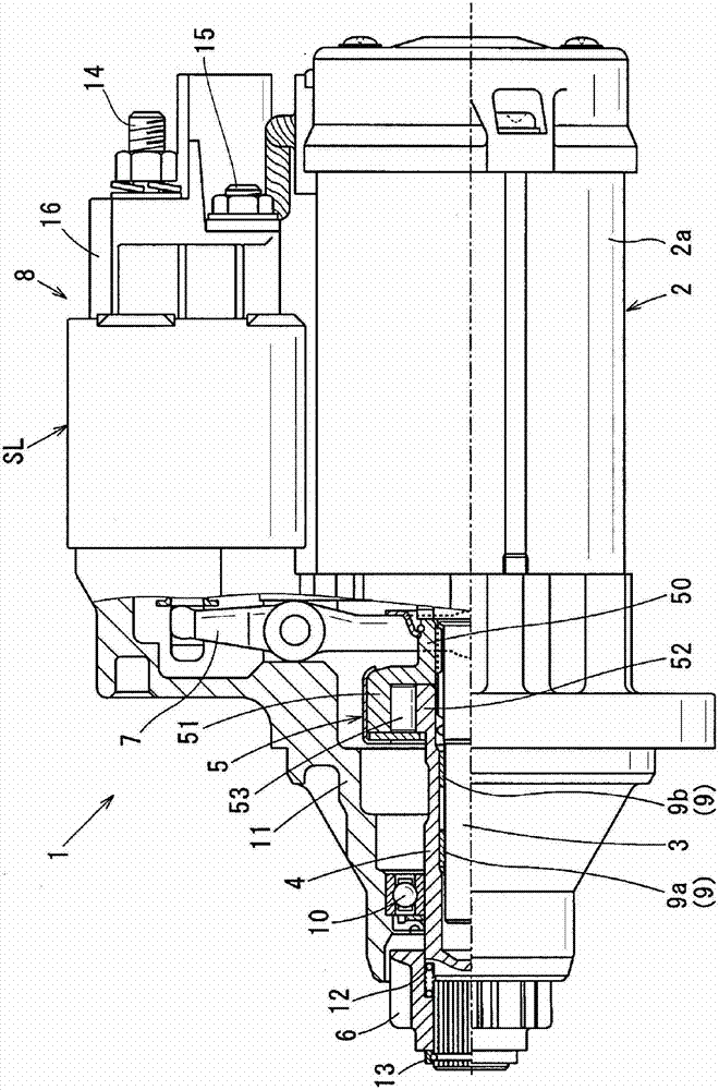
[0034] figure 1 A starter 1 according to a first embodiment is shown. Such as figure 1 As shown, the starter 1 includes a motor 2 , an output shaft 3 , a pinion tube 4 , a clutch 5 , a pinion 6 and an electromagnetic switch 8 . The motor 2 receives supplied electric power to generate torque. The output shaft 3 is driven to rotate by the motor 2 . The pinion tube 4 is fitted on the outer periphery of the output shaft 3 with a spline connection. The clutch 5 transmits the rotation of the output shaft 3 to the pinion tube 4 . The pinion 6 is supported at the end on the anti-motor side in the axial direction of the pinion tube 4 . The electromagnetic switch 8 has a function of driving the shift lever 7 by the attractive force of the electromagnet so that the pinion tube 4 faces the anti-motor side in the axial direction with the clutch 5 with respect to the output shaft 3 ( figure 1to the left of the ) shift. In addition, the electromagnetic switch 8 opens and closes mai...

no. 2 approach

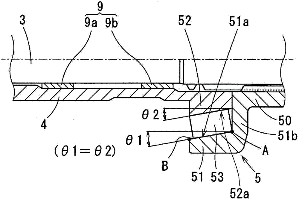
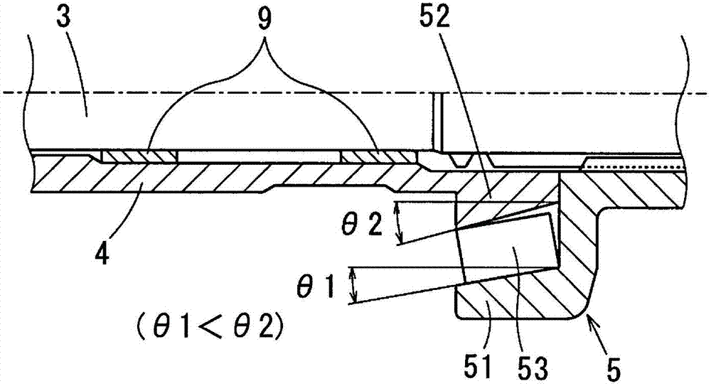
[0058] In the first embodiment, if figure 2 As shown, the taper angle θ1 of the inner portion 52 is set to be equal to the taper angle θ2 of the outer portion 51 (θ1=θ2). In the second embodiment, as image 3 As shown, the taper angle θ1 of the interior 52 is set to be smaller than the taper angle θ2 of the exterior 51 (θ1 Figure 4 As shown, the taper angle θ1 of the inner portion 52 is set larger than the taper angle θ2 of the outer portion 51 (θ1>θ2).

[0059] In both cases above, the outer periphery 52a of the inner portion 52 is provided in a tapered shape, so the gap between the roller 53 and the inner portion 52 formed by the tapered shape of the cam surface 51a can be reduced. Thus, when torque is transmitted, the inclination of the pinion tube 4 , that is, the inclination of the inner portion 52 relative to the roller 53 can be reduced. Thus, it is possible to prevent the roller 53 and the inner portion 52 from contacting each other only at the bottom of the cam. T...


PUM


Abstract

The invention provides a starter which is provided with a spline cylinder, an outer part, an inner part, and a roller clutch. The spline cylinder is connected and assembled at the outer periphery of an output shaft by a spiral spline. The outer part is integrally disposed with the spline cylinder, and forms a cam chamber. The inner part is integrally disposed with an end part of a pinion pipe, and is disposed at the radial inside of the outer part. A roller is disposed in the cam chamber between the outer part and the inner part. In the starter, the outer part has a cone shape to allow the inner diameter of the outer part forming the cam chamber to increase gradually from an opposite pinion side to the pinion side in an axial direction. The inner part has a periphery which has a cone shape with a diameter decreasing gradually from the pinion side to the opposite pinion side in the axial direction.

Description

technical field [0001] The present invention relates to a starter, and more particularly, to a starter using a system in which a pinion tube fitted on the outer circumference of an output The end-supported clutches at the motor side move forward together in the axial direction towards the anti-motor side, so that the pinion meshes with the ring gear of the engine. Background technique [0002] As a related art, a starter called "cantilever support structure" is disclosed in JP-A-2002-180936. Such as Figure 5 As shown, the starter includes an output shaft 100 , a pinion tube 120 , a roller type one-way clutch 130 , a pinion 140 and a housing 160 . The output shaft 100 is driven to rotate by a motor (not shown). The pinion tube 120 is fitted on the outer periphery of the output shaft 100 through bearings (sliding bearings). The clutch 130 transmits the rotation of the output shaft 100 to the pinion tube 120 . The pinion gear 140 is fitted on the anti-motor side of the pin...

Claims


Application Information

Patent Timeline
IPC IPC(8): F02N11/00F02N15/06
CPCF02N11/00F02N15/025F02N15/026F02N15/063F02N15/067
Inventor 宫武知史今西友也
Owner DENSO CORP
Why Eureka
Try Eureka