System for collecting and utilizing compressed-air type wave energy of ship swaying lever

An energy harvesting and lever technology, which is used in liquid variable capacity machinery, piston pumps, pump devices, etc., can solve the problems of increased manufacturing costs, low energy conversion equipment, and inability to meet the requirements of reducing corrosion resistance. Avoid direct impact and erosion, reduce the effect of investment in capital costs

Active Publication Date: 2013-04-10
李宁
View PDF5 Cites 2 Cited by
  • Summary
  • Abstract
  • Description
  • Claims
  • Application Information

AI Technical Summary

Problems solved by technology

[0004] The existing wave energy conversion equipment is difficult to install and construct on the sea surface, with high risks, low reliability and difficult maintenance
[0005] 2. High material and process requirements
[0006] The existing wave energy conversion equipment is directly in contact with seawater. In order to use seawater to directly drive the conversion equipment, due to the strong corrosion of seawater, the requirements for materials and processes are very high. As a result, the manufacturing cost is greatly increased, and the working stability is poor and the service life is short
[0007] 3. Low conversion rate
[0008] Current conversion equipment obtains very little energy, ranging from tens to hundreds of kilowatts, which cannot meet people's needs
[0009] Many shortcomings of the prior art have restricted people's development of ocean wave energy

Method used


Image

  • System for collecting and utilizing compressed-air type wave energy of ship swaying lever

Examples


Embodiment Construction

[0024] Below in conjunction with accompanying drawing, technical scheme of the present invention will be further described:

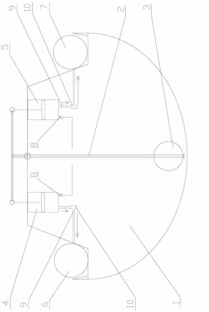
[0025] The ship swing lever compressed air type wave energy collection and application system of the present invention includes an energy conversion and collection device that converts the kinetic energy of the left and right swings of the ship body 1 into compressed air energy and collects it. The energy conversion and collection device is mainly composed of a T-shaped lever 2, a counterweight 3, The left cylinder 4 and the right cylinder 5 (the same type and specification), the left air storage tank 6 and the right air storage tank 7 (the same size), valves and pipelines 9 constitute.

[0026] The vertical bar of the T-shaped lever 2 is located on the center line of the hull 1 and the hull 1 is divided into two parts, left and right. The upper part of the vertical rod is hinged on the hull 1, and the counterweight 3 is arranged at the bottom of the ve...


PUM


Abstract

The invention discloses a system for collecting and utilizing compressed-air type wave energy of a ship swaying lever. An energy converting and collecting device comprises a T-shaped lever, a cylinder and an air storage tank, wherein a vertical rod of the T-shaped lever is arranged in the right middle of a ship body; the upper part of the vertical rod is hinged; a counterweight is arranged at the lower part of the vertical rod; the cylinder is a left cylinder and a right cylinder which are respectively arranged on a left ship body and a right ship body on the two sides of the vertical rod; piston rods of the left cylinder and the right cylinder are respectively connected with a left end and a right end of a cross rod of the T-shaped lever; the air storage tank is a left air storage tank and a right air storage tank; corresponding to the left cylinder and the right cylinder, the left air storage tank and the right air storage tank are respectively arranged on the left ship body and the right ship body; an air inlet valve and an air outlet valve both communicated with atmosphere are arranged on the cylinder; and the air outlet valve is communicated with the corresponding air storage tank through a pipeline. According to the invention, as the converting and collecting device is mounted in the ship body and is not in direct contact with seawater, the direct impact and erosion of the seawater on the device are avoided, the capital investment is reduced, the economic efficiency is greatly increased, the service life is greatly prolonged and convenience for daily maintenance of the device is provided.

Description

(1) Technical field: [0001] The invention relates to the conversion and collection of energy, in particular to a system for collecting and utilizing wave energy of a ship's rocking lever and compressed air, which utilizes wave energy. (2) Background technology: [0002] The wave energy conversion equipment of the prior art has been developed and used, but it has the following defects: [0003] 1. The construction is difficult. [0004] The existing wave energy conversion equipment is difficult to install and construct on the sea surface, has high risks, low reliability, and is quite difficult to maintain. [0005] 2. High requirements for material technology. [0006] The existing wave energy conversion equipment is directly in contact with seawater. In order to use seawater to directly drive the conversion equipment, due to the strong corrosion of seawater, the requirements for materials and processes are very high. Therefore, the manufacturing cost is greatly increased,...

Claims


Application Information

Patent Timeline
Patent Type & Authority Applications(China)
IPC IPC(8): F04B35/02F04B41/06F04B41/02
Inventor 李宁
Owner 李宁
Why Eureka
Try Eureka