
Ceramic composite insulator, mould and manufacturing process

A technology of porcelain composite insulators and porcelain insulators, which is applied in the field of power transmission and transformation, can solve the problems of failure to maximize the improvement of pollution resistance, the joint surface cannot ensure no air gap channels, and insufficient electrical insulation, so as to achieve reliable electrical performance, Good insulation performance and strong combination effect

Inactive Publication Date: 2013-04-10
HEBEI SILICON VALLEY CHEM CO LTD
View PDF5 Cites 5 Cited by
  • Summary
  • Abstract
  • Description
  • Claims
  • Application Information

AI Technical Summary

Problems solved by technology

The "composite insulator" of this document has two disadvantages: one is that the shed that increases the creepage distance is still bonded to the porcelain insulator with an adhesive, and the durability (life) of the adhesive is much lower than that of porcelain and shed. High-temperature vulcanized rubber, and the complex shape of the joint surface cannot ensure that there is no air gap after bonding, and there is a hidden danger of insufficient electrical insulation, which is a taboo in the high-voltage industry; The surface of the porcelain is all composited, which fails to maximize its anti-fouling performance

Method used


Image

  • Ceramic composite insulator, mould and manufacturing process
  • Ceramic composite insulator, mould and manufacturing process
  • Ceramic composite insulator, mould and manufacturing process

Examples


Embodiment Construction

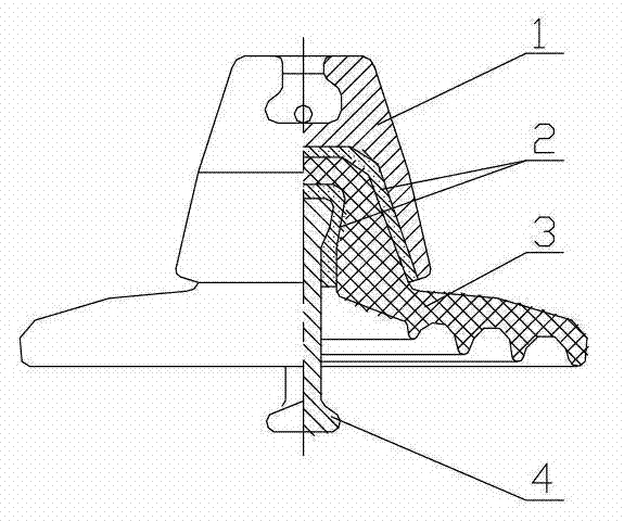
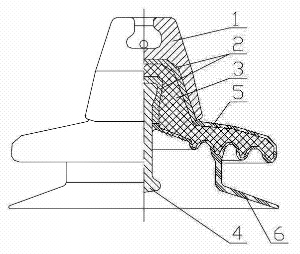
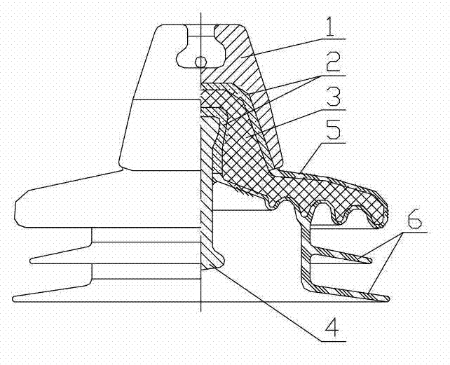
[0016] Figure 1-5 Middle: 1. Steel cap, 2. Adhesive cement, 3. Porcelain parts, 4. Steel feet, 5. Rubber sheath, 6. Rubber shed, 7. Outer sheath clearance, 8. Shed clearance, 9. Left module, 10, right module, 11, lower module, 12, inner sheath gap.

[0017] Such as Figure 1-3 As shown, a porcelain composite insulator includes a standard porcelain insulator, a rubber sheath 5 and a rubber shed 6. The porcelain insulator includes a steel cap 1, a porcelain part 2 and a steel foot 4, and a steel cap 1, a porcelain part 2 and a steel foot. 4 are firmly fixed by bonding cement 3; the exposed outer surface of the porcelain part 2 of the porcelain insulator has a rubber sheath 5 tightly combined with the porcelain part.

[0018] The rubber sheath 5 has a rubber shed 6 integrated with the rubber sheath 5 at the lower end of the porcelain part 2 . The number of the rubber sheds 6 is 1 or 2. Such as figure 2 , 3 shown.

[0019] The materials of the rubber sheath 5 and the rubb...


PUM


Abstract

The invention relates to a ceramic composite insulator, a mould and a manufacturing process. The ceramic composite insulator comprises a ceramic insulator, a rubber protective sleeve and a rubber umbrella surface, the ceramic insulator comprises a steel cap, a ceramic piece and a steel foot, the steel cap, the ceramic piece and the steel foot are solidly fixed through adhesive cement, and the exposed outer surface of the ceramic piece of the ceramic insulator is provided with the rubber protective sleeve tightly combined with the ceramic piece. The mould producing the ceramic composite insulator comprises a left mould, a right mould and a lower mould. The process manufacturing the ceramic composite insulator comprises the following steps: placing the ceramic insulator in the mould, installing the mould on a rubber injection machine and carrying out heating to rise temperature; locking the mould tightly, and vacuumizing the mould; injecting rubber to a mould cavity formed by an outer protective sleeve clearance, an inner protective sleeve clearance and an umbrella surface clearance through pressure, and maintaining pressure to carry out vulcanization; releasing the pressure and demoulding. The ceramic composite insulator, the mould and the manufacturing process can meet the insulating needs of the heavy polluted environment of the overhead transmission line of an electrical power system.

Description

technical field [0001] The invention relates to the structural design and manufacturing process of a composite insulator, in particular to the factory composite of disc-shaped suspension porcelain or glass insulators, and belongs to the technical field of power transmission and transformation. Background technique [0002] The insulation support of high-voltage overhead transmission line conductors in power systems is mainly performed by disc-shaped suspension porcelain insulators or glass insulators (hereinafter referred to as porcelain [or glass] insulators, also known as insulators). Ordinary disc suspension insulators include standard and large creepage insulators, which are mainly suitable for clean areas and lightly polluted areas. In order to meet the needs of use in heavily polluted areas, bell-type insulators have a large creepage distance, but poor self-cleaning ability, which is difficult to meet the needs. [0003] For this reason, the birth of rod-shaped compos...

Claims


Application Information

Patent Timeline
IPC IPC(8): H01B17/38H01B17/42H01B19/00
Inventor 宋利强游传榜
Owner HEBEI SILICON VALLEY CHEM CO LTD
Learn More