Detection method of permanent magnet motor rotor position

A permanent magnet motor, rotor position technology, applied in motor generator control, control of electromechanical transmission, electronic commutation motor control, etc. The requirements are higher

Active Publication Date: 2013-04-10
ZHEJIANG UNIV
View PDF7 Cites 28 Cited by
  • Summary
  • Abstract
  • Description
  • Claims
  • Application Information

AI Technical Summary

Problems solved by technology

This method is widely used in the field of position sensorless control technology of motors, and the technology is relatively mature, but the intermediate quantities in the calculation process are all AC quantities, which require relatively high calculation speed and accuracy for the processor, and are easily affected by the intermediate Influence of amplitude-frequency characteristic and phase-frequency characteristic of link filter
For the hidden pole permanent magnet motor, the calculation process of this algori

Method used


Image

  • Detection method of permanent magnet motor rotor position
  • Detection method of permanent magnet motor rotor position
  • Detection method of permanent magnet motor rotor position

Examples


Embodiment Construction

[0046] In order to describe the present invention more specifically, the detection method of the present invention will be described in detail below in conjunction with the accompanying drawings and specific embodiments.

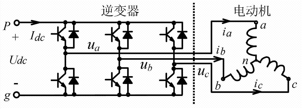
[0047] Taking a three-phase permanent magnet synchronous motor as an example, the parameters of the motor are shown in Table 1; the control structure of the motor is as follows figure 1 As shown, among them, U a , U b , U c is the three-phase terminal voltage, I a , I b , I c is the three-phase current.

[0048] Table 1

[0049] Rated power (W)

1500

Rated speed(rpm)

1000

Rated torque(N*m)

14.3

Rated current (A)

3.8

Winding Connection

Y type

Phase resistance R s (Ω)

2.15

Direct axis inductance L d (H)

0.0632

Quadrature axis inductance L q (H)

0.0919

Permanent magnet equivalent flux linkage (Wb)

0.5

[0050] A method for detecting the rotor ...


PUM


Abstract

The invention discloses a detection method of a permanent magnet motor rotor position. The detection method comprises: (1) calculating alpha and beta weight of a stator flux linkage; (2) setting up auxiliary d'-q' coordinate system; (3) figuring out angle from d' axis to d axis, and then obtaining position information of the rotor. By introducing the auxiliary d'-q' coordinate system which has same position angle with the stator flux linkage vector and same revolving speed with a d-q coordinate system, physical quantities in the coordinate system are all direct current when the coordinate system is operated in a steady state, thereby simplifying computation process, and reducing requests to a processor and a sensor. Calculation error is smaller due to the fact that influence of a filter can be basically ignored. Meanwhile calculation can automatically adjust according to the former calculation, and correct an inductance timely, so that final error is lessened.

Description

technical field [0001] The invention belongs to the technical field of motors, and in particular relates to a method for detecting the rotor position of a permanent magnet motor. Background technique [0002] To accurately control the motion state of the permanent magnet synchronous motor, it is necessary to know the real-time rotor position signal of the motor, so the traditional permanent magnet motor generally uses an additional position sensor to detect the rotor position. However, the use of a position sensor not only increases the cost and the complexity of the motor structure, but also in some high temperature, high pressure or strong corrosive environments, the position sensor will reduce the reliability of the system or the sensor will not work properly. Therefore, realizing the position sensorless control of permanent magnet synchronous motor has become one of the important directions in the development of permanent magnet motor control technology in recent years. ...

Claims


Application Information

Patent Timeline
IPC IPC(8): H02P21/14H02P21/18
Inventor 沈建新李鹏孙伟王康
Owner ZHEJIANG UNIV
Why Eureka
Try Eureka