
Tilt-shift tomography eye scanning system and method thereof

A scanning system and eye technology, used in eye testing equipment, diagnosis, medical science, etc., can solve problems such as loss of light, easy eye rotation, and inability to image, and achieve improved measurement accuracy, improved shooting effects, and improved consistency. Effect

Inactive Publication Date: 2013-04-17
SHANGHAI MEDIWORKS PRECISION INSTR CO LTD
View PDF7 Cites 0 Cited by
  • Summary
  • Abstract
  • Description
  • Claims
  • Application Information

AI Technical Summary

Problems solved by technology

[0003] 1. In the case of out-of-focus visual targets, the subject's line of sight has no definite direction, and the eyeballs are easy to rotate, which affects the inspection results
[0004] 2. In foreign countries, there are also focusing targets, but they are generally realized by marking symbols on the projection optical lens. If the focusing targets provided by this method are too small, it is difficult for the patient’s eyes to find them. If they are too large, the patient’s gaze range may be too large. Not only the staring effect is not very good, but also it is easy to disturb and lose light, affect the illumination, thus affect the shooting effect of the camera, and then affect the measurement results; in addition, it is not convenient to adjust the position of the focusing target
[0005] 3. As announced on September 15, 2010, the Chinese invention patent with the publication number CN 101828900 A provides "a shift-axis tomography device", which well realizes the function of rotating scanning photography, and its claim 1 clearly describes " The center of rotation of the rotating disk (1-18) coincides with the center of the focusing optical path of the focusing optical path equipment", and its claim 3 clearly states that "there are 2 to 4 red light-emitting diodes on the beam splitting prism (1-6)" , but in the technology of using the red light emitted by the red diode in the center of the optical path to focus, if the patient's eyes use the red diode as the light source for the visual target, the patient's eye axis is facing the entire device, and the red diode is located in the center of the dichroic prism, which will inevitably block The slit projected optical path on the main optical path makes it impossible to image near the middle of the image captured by the rotating camera and the focusing camera, and the whole device cannot well complete the stereoscopic imaging function of the parts near the eye axis; and the red diode is located on the edge of the dichroic prism When using multiple diodes, the eyes will inevitably be unable to stare due to the scattered distribution of the staring targets, so in these cases the entire device cannot complete the staring, focusing and shooting functions that are completely aligned.
[0006] In addition, the method of "focusing optical path equipment set on the rotating disk (1-18)" clearly stated in claim 1 will make the power supply cables of "focusing optical path equipment" such as "red light emitting diodes" follow the rotating disk ( 1-18) rotation, which limits the number of rotations of the rotary disc (1-18), and the cable is frequently pulled and easily damaged. Even if the power supply is rotated through the carbon brush, the carbon brush is prone to failure or damage, and always need frequent replacement
[0007] At present, there is no axis-shift tomographic eye that overcomes the above defects and can not only provide focusing targets, but also has comprehensive focusing effects, better staring effects, higher imaging quality, unlimited number of rotations, and higher equipment reliability. Scanning system and method

Method used


Image

  • Tilt-shift tomography eye scanning system and method thereof
  • Tilt-shift tomography eye scanning system and method thereof
  • Tilt-shift tomography eye scanning system and method thereof

Examples


Embodiment Construction

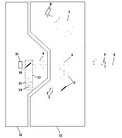
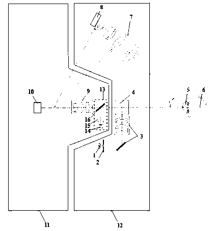
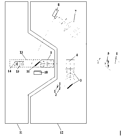
[0032] The specific embodiment of the present invention will be further elaborated below in conjunction with accompanying drawing:

[0033] figure 1 In this system, the system includes a light source 1, a slit diaphragm 2, a projection lens group 3, a color separation reflective device 4, an anterior tissue of the eye 5, an eye 6, a tilt-shift imaging lens 7, a tilt-shift camera 8, a focus lens 9, and a focus camera 10 , a fixed bracket assembly 11, a rotating disk assembly 12.

[0034] A focus optic optical path device 13 is also provided; the focus optic optical path device 13 is arranged on the fixed bracket assembly 11 to provide a gaze target for the eye 6 and basically fix the anterior tissue 5 of the eye.

[0035] The optical axis of the focus optic optical path device 13 may be perpendicular to the central axis of the rotating disk assembly 12 ; correspondingly, the optical axis of the focusing camera 10 may coincide with the central axis of the rotating disk asse...


PUM


Abstract

The invention discloses a tilt-shift tomography eye scanning system and a method thereof, relates to the field of optical instruments for the ophthalmology, and aims at solving the problem of eye fixation during focusing. The scanning system comprises a light source (1), a fracture diaphragm (2), a projecting mirror group (3), a color-separating reflective device (4), eye forepart tissues (5), an eye (6), tilt-shaft imaging lenses (7), tilt-shift cameras (8), focusing lenses (9), focusing cameras (10), a fixed support assembly (11), and a rotary disc assembly (12). A focusing sighting mark optical path device (13) is further arranged; can comprise a focusing sighting mark light source (14), a focusing sighting mark projection lens (15) and a color-separating reflective mirror (16); is installed on the fixed support assembly (11); and provides gaze sighting marks for the eye (6) to enable the eye forepart tissues (5) to be basically fixed. The tilt-shift tomography eye scanning system and the method thereof are mainly used for examining eye forepart tissues.

Description

technical field [0001] The invention relates to the field of ophthalmic optical instruments, in particular to an axis-shifting tomographic eye scanning system and a method thereof. Background technique [0002] The current shift tomography eye scanning system generally has the following specific defects: [0003] 1. In the case of out-of-focus visual targets, the subject's line of sight has no definite direction, and the eyeballs are easy to rotate, which affects the inspection results. [0004] 2. In foreign countries, there are also focusing targets, but they are generally realized by marking symbols on the projection optical lens. If the focusing targets provided by this method are too small, it is difficult for the patient’s eyes to find them. If they are too large, the patient’s gaze range may be too large. Not only the staring effect is not very good, but also it is easy to disturb and lose light, affect the illumination, thus affect the shooting effect of the camer...

Claims


Application Information

Patent Timeline
Patent Type & Authority Applications(China)
IPC IPC(8): A61B3/14
Inventor 王宏良严苏峰魏悦陈文光孔昭松
Owner SHANGHAI MEDIWORKS PRECISION INSTR CO LTD
Learn More