
Valve rod for high-temperature high-pressure stop valve and machining method of valve rod

A high-temperature, high-pressure, processing method technology, applied in the direction of valve devices, cocks including cut-off devices, engine components, etc., can solve the problems of small application range of valve stem heads, increased maintenance costs, poor adjustment performance, etc., and achieve good mechanical properties Requirements and product quality, material cost saving, and the effect of short opening and closing time

Inactive Publication Date: 2014-08-13
SUZHOU SAIHUA INSTR CONTROL CO LTD
View PDF9 Cites 1 Cited by
  • Summary
  • Abstract
  • Description
  • Claims
  • Application Information

AI Technical Summary

Problems solved by technology

However, in the current domestic high-temperature and high-pressure globe valve market, in addition to low-end valves reaching the level acceptable to the international market, high-end valves still have a large gap compared with foreign manufacturers in precision processing technology and high-temperature material research. Rely on imports
[0003] In the prior art, the stem head of the general globe valve is plug-shaped, the sealing surface is flat or conical, and the stem head and the stem are fixedly welded together, but such a structural design is difficult to open and close. The fluid resistance encountered is relatively large, and the force required for opening and closing is relatively large, and due to the shape characteristics of the valve stem head, the applicable range of the valve stem head is small, and the adjustment performance is poor, and when the valve stem head is damaged, it needs to be replaced. The whole valve stem increases the maintenance cost

Method used


Image

  • Valve rod for high-temperature high-pressure stop valve and machining method of valve rod
  • Valve rod for high-temperature high-pressure stop valve and machining method of valve rod
  • Valve rod for high-temperature high-pressure stop valve and machining method of valve rod

Examples


Embodiment 1

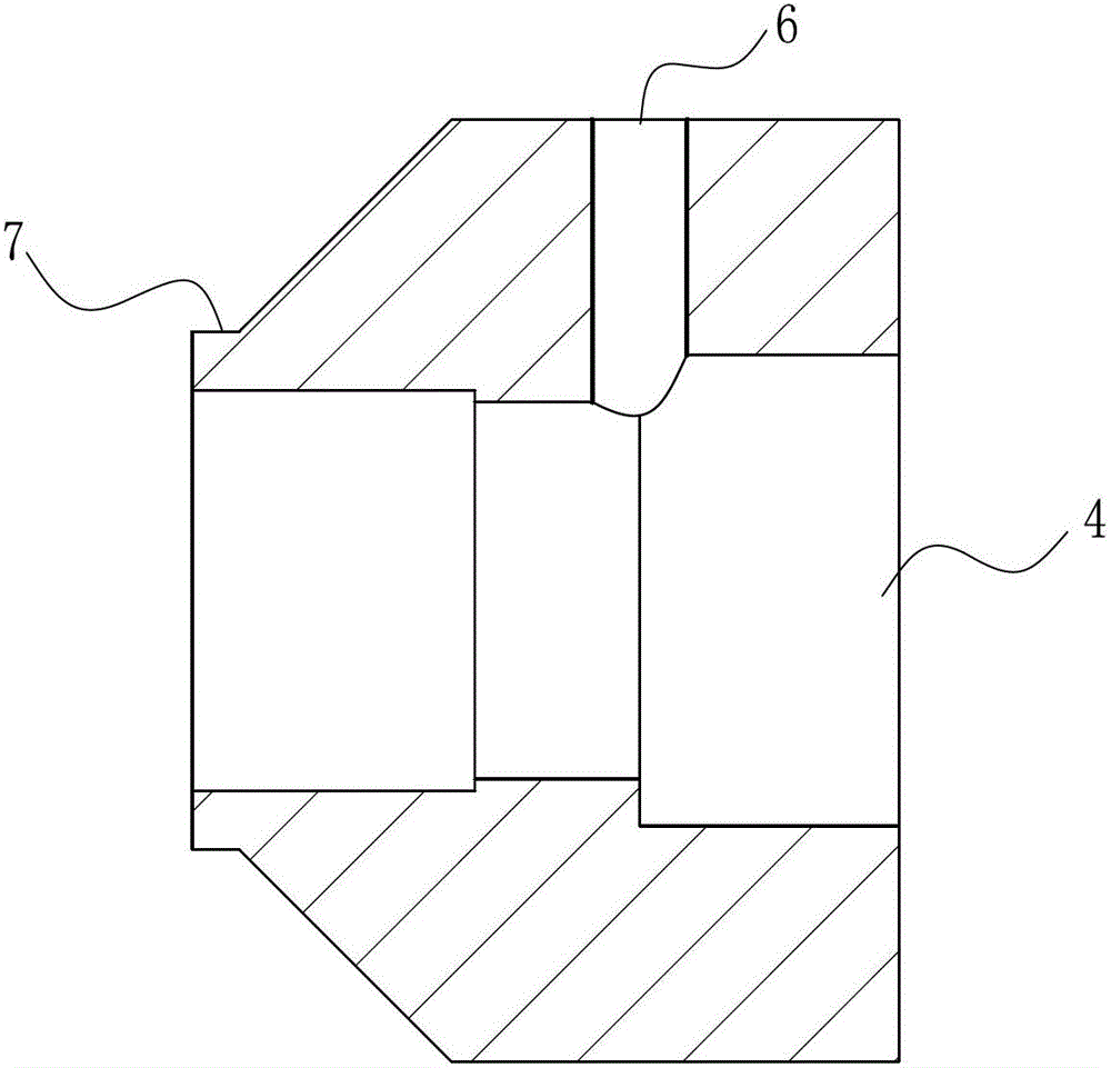
[0025] Embodiment one: see attached Figure 1-3 shown.

[0026] A valve stem for a high-temperature and high-pressure globe valve, which includes a valve stem main rod 1, a valve ball cap 2 fixedly arranged at one end of the valve stem main rod 1, a valve ball 3 freely rotatably arranged in the valve ball cap 2, and a valve ball 3 One end protrudes outside the valve ball cap 2, and the ball center of the valve ball 3 is located on the axis of the main rod 1 of the valve stem.

[0027] A method for processing a valve stem for a high-temperature, high-pressure globe valve, comprising the following steps:

[0028] Take the pipe material for solid solution treatment, the solution temperature is ≧1040°C, use the three-jaw chuck to find the coaxial clamping pipe material and ensure the clamping, and the two ends of the pipe material are smooth and flat, and the outer circle of the pipe material is φ20mm× 18mm, bore the inner hole of the valve ball cap 4φ10mm×5.5mm in the center of...


PUM


Abstract

The invention discloses a valve rod for a high-temperature high-pressure stop valve and a machining method of the valve rod. The valve rod comprises main valve rod, a valve ball cap fixedly disposed at one end of the main valve rod, and a valve ball disposed in the valve ball cap in a free rotation manner. One end of the valve ball protrudes out of the valve ball cap. A spherical center of the valve ball is located on an axis of the main valve rod. The machining method includes machining the valve ball cap, welding the main valve rod, machining the inner spherical face and the valve rod, and assembling the valve ball. By the valve rod which is simple in structure, airtightness, impact resistance, corrosion resistance and operation reliability of valves in high-temperature high-pressure environments are improved.

Description

technical field [0001] The invention relates to a valve stem structure and a manufacturing process, in particular to a valve stem for a small-diameter high-temperature and high-pressure stop valve and a processing method thereof. Background technique [0002] At present, high-temperature and high-pressure globe valves have become indispensable fluid control equipment in industries such as nuclear industry, thermal power, petroleum, chemical industry, pipeline, shipbuilding, aerospace, and marine oil production. Most of the process systems in the above-mentioned industries need to be equipped with special valves. In particular, some high-end valves, such as high-temperature and high-pressure globe valves with a temperature resistance above 600°C and a pressure resistance above 30Mpa, are generally located in key parts of the process system. It will affect the realization of the function of the process system, causing the load reduction or even shutdown of the above-mentioned ...

Claims


Application Information

Patent Timeline
Patent Type & Authority Patents(China)
IPC IPC(8): F16K5/08B23P15/00
Inventor 宋建中
Owner SUZHOU SAIHUA INSTR CONTROL CO LTD
Learn More