Magnetic-suspension wave detector

A geophone and magnetic levitation technology, applied in the direction of seismic signal receivers, etc., can solve the problems of affecting sensitivity and accuracy, difficult to overcome and improve, unable to meet high monitoring sensitivity, high precision and other problems

Active Publication Date: 2013-04-17
丹东大东线圈工程有限公司
View PDF3 Cites 9 Cited by
  • Summary
  • Abstract
  • Description
  • Claims
  • Application Information

AI Technical Summary

Problems solved by technology

[0003] Due to the constraints of inherent conditions such as the quality of the shrapnel (spring) and the stubbornness coefficient, the shrapnel itself will have a certain loss, which will affect the sensitivity and accuracy of monitoring, and it is difficult to overcome and improve, and cannot meet the fields of high monitoring sensitivity and high precision. needs
[0004] like figure 2 As shown, for the magnetic levitation detector, the magnetic levitation body 15 needs to block the magnetic levitation body shaft 17 by means of contact with auxiliary parts such as the shaft sleeve 16, so as to ensure that the magnetic levitation body shaft 17 can only move in the up and down direction without contact. There must be friction and loss, and frictional resistance will affect the sensitivity and accuracy of monitoring, so figure 2 The magnetic levitation detector shown still cannot meet the needs of high monitoring sensitivity, high precision and other fields

Method used


Image

  • Magnetic-suspension wave detector
  • Magnetic-suspension wave detector
  • Magnetic-suspension wave detector

Examples


Embodiment Construction

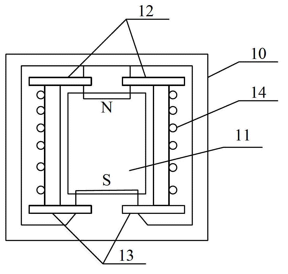
[0032] Embodiments of the present invention will be described in detail below in conjunction with the accompanying drawings.

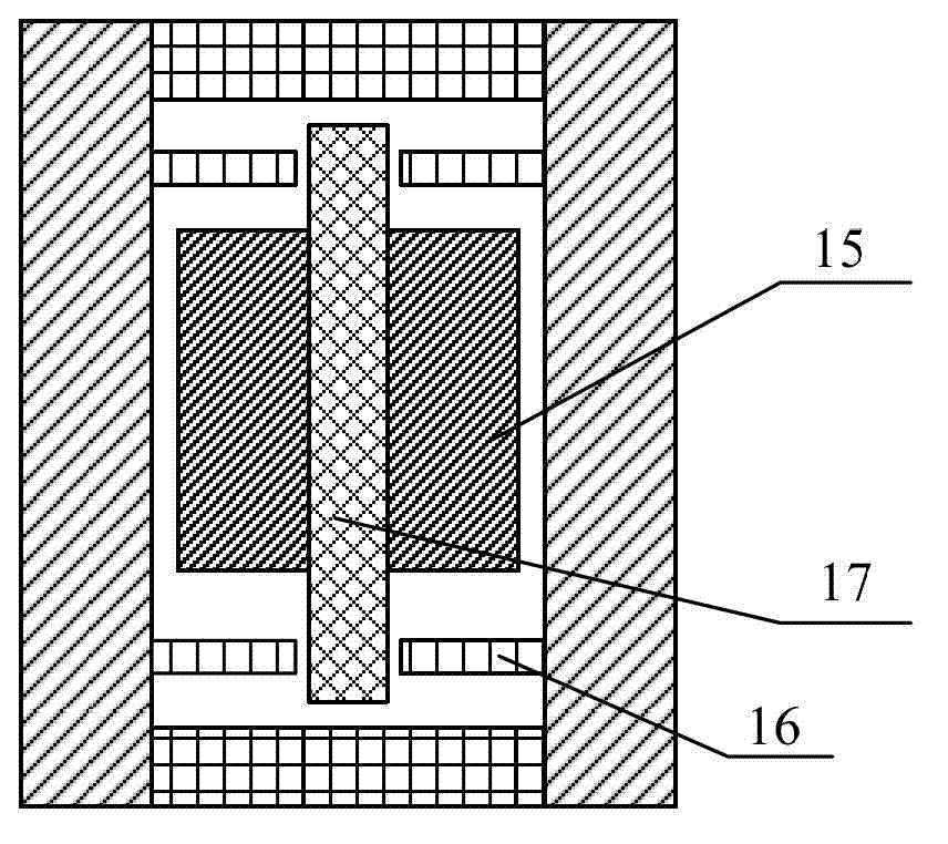
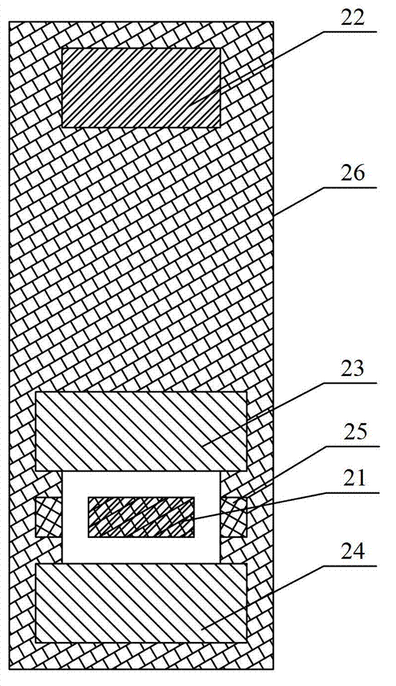
[0033] Such as image 3 , Figure 4 As shown, the magnetic levitation detector provided by the embodiment of the present invention includes: a levitating permanent magnet 21, a fixed permanent magnet 22, two anti-magnets (including a first anti-magnet 23 and a second anti-magnet 24), a coil 25 and a housing 26 ( Figure 4 not shown).

[0034] Wherein, the fixed permanent magnet 22 , the first anti-magnet 23 , the coil 25 and the second anti-magnet 24 are sequentially arranged inside the housing 26 from top to bottom. Preferably, the above-mentioned components are located in the same vertical axis direction. The suspended permanent magnet 21 is suspended in the coil 25 . The two magnetic poles of the fixed permanent magnet 22 and the floating permanent magnet 21 are respectively located on the upper surface and the lower surface thereof, and the two ...


PUM


Abstract

The invention provides a magnetic-suspension wave detector. The magnetic-suspension wave detector comprises a shell, a fixed permanent magnet, a first diamagnetic body, a coil, a second diamagnetic body and a suspension permanent magnet, wherein the fixed permanent magnet, the first diamagnetic body, the coil and the second diamagnetic body are sequentially arranged at the inner part of the shell from top to bottom, the suspension permanent magnet is positioned in the coil, and the magnetic pole magnetisms of the fixed permanent magnet and the suspension permanent magnet facing each other are different. According to the magnetic-suspension wave detector provided by the invention, the gravity born by the suspension permanent magnet can be offset through an attraction force from the fixed permanent magnet to the suspension permanent magnet, and the suspension permanent magnet is guaranteed to be in a stable state through the diamagnetic bodies which are positioned at the upper part and the lower part of the suspension permanent magnet; and when the suspension permanent magnet shifts to optional one direction, a component force of a horizontal direction or a vertical direction of a resulting force born by the suspension permanent magnet is opposite to a shifting direction, thus the suspension permanent magnet can be quickly and accurately attracted to return to a balance position, and the sensitivity and the accuracy of monitoring are increased.

Description

technical field [0001] The invention relates to the technical field of geophones, in particular to a magnetic levitation geophone used for monitoring earthquakes, deep seas or bridges. Background technique [0002] In technical fields such as mechanical vibration monitoring, key indicators such as monitoring sensitivity and monitoring accuracy mainly depend on the physical structure of the geophone. Taking the most widely used moving coil detector as an example, such as figure 1 As shown, the moving coil detector includes a casing 10 , a coil 14 suspended in the casing 10 by an upper elastic piece 12 and a lower elastic piece 13 , and a magnetic steel 11 located in the coil 14 . The principle of the moving coil detector is to use the elastic force of the upper elastic piece 12 and the lower elastic piece 13 to offset the gravity on the coil 14 itself, so that the coil 14 is in a balanced state. When the detector moves with the measured object, the coil 14 will be displaced...

Claims


Application Information

Patent Timeline
Patent Type & Authority Applications(China)
IPC IPC(8): G01V1/18
Inventor 郭为民莫宇涵孙宇昌付生奇
Owner 丹东大东线圈工程有限公司
Why Eureka
Try Eureka