A geogrid welding machine

A geogrid, welding machine technology, applied in welding equipment, auxiliary welding equipment, welding/cutting auxiliary equipment, etc., can solve the problems of difficult to guarantee welding quality and low production efficiency.

Active Publication Date: 2016-12-28
SUZHOU KEBER PRECISION MACHINERY
View PDF5 Cites 0 Cited by
  • Summary
  • Abstract
  • Description
  • Claims
  • Application Information

AI Technical Summary

Problems solved by technology

The production of geogrids is produced manually, the production efficiency is low, and the welding quality is difficult to guarantee; therefore, it is urgent to develop a geogrid welding machine that can automatically feed, automatically cut, and automatically weld

Method used


Image

  • A geogrid welding machine
  • A geogrid welding machine
  • A geogrid welding machine

Examples


Embodiment Construction

[0019] The present invention will be further described in detail below in conjunction with the accompanying drawings and specific embodiments.

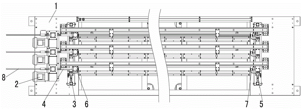
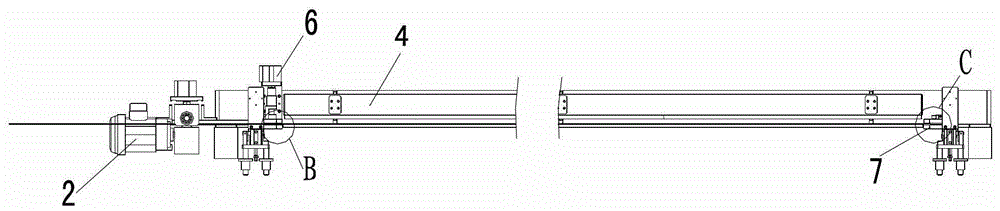
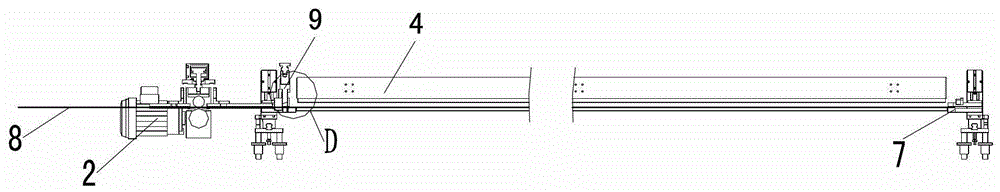
[0020] attached Figure 1-9 It is a geogrid welding machine according to the present invention, including a controller (not shown), a base 1, a feeding device 2, a first guide rail 3, a material guide device 4, a second guide rail 5, and a first clamping device 6. The second clamping device 7, the upper mold 13; the base 1 is provided with lower molds 10 evenly spaced along the longitudinal direction; a plurality of welding heads (not shown) are evenly spaced directly above the lower mold 10 ), so that each welding head is just located at the overlap of the horizontal strip and the longitudinal strip; the first guide rail 3 is arranged on the base 1 and is located on one side of the lower mold 10; the second guide rail 5 It is arranged on the base 1 and is located on the other side of the lower mold 10; the first clamping device 6 is...


PUM


Abstract

The invention discloses a geogrid welding machine. When a feeder transversely sends materials, the materials are fed into a second clamping device along a leading device; when the materials reach a preset position in the second clamping device, the feeder stops working under control of a controller. At the same time, a first clamping device and the second clamping device can respectively clamp the two ends of the materials, then the controller controls a trimming device to cut off the materials, afterwards, the controller controls a first cylinder to enable the first clamping device and the second clamping device to move along their own guide rails and enable the materials to be disposed right above a lower die and right under an upper die. At this moment, a second cylinder moves under control of the controller to enable the upper die to depress the materials down on the lower die. Then a plum joint under control of the controller welds the tap of a transverse strip belt and a longitudinal strip belt. The geogrid welding machine has the advantages of automatic feeding, automatic cutting and automatic welding.

Description

technical field [0001] The invention relates to an improvement of a welding device, in particular to a geogrid welding machine capable of automatic feeding, automatic cutting and automatic welding. Background technique [0002] The geogrid includes a transverse strip and a longitudinal strip; the transverse strips are multiple and uniformly distributed along the transverse direction; the longitudinal strips also have multiple longitudinal strips and are uniformly distributed along the longitudinal direction; The lap joints of the longitudinal strips are welded to fix them to each other. The manual production of geogrids has low production efficiency, and the welding quality is difficult to guarantee; therefore, it is urgent to develop a geogrid welding machine that can automatically feed, automatically cut, and automatically weld. Contents of the invention [0003] The object of the present invention is to provide a geogrid welding machine capable of automatic feeding, au...

Claims


Application Information

Patent Timeline
Patent Type & Authority Patents(China)
IPC IPC(8): B23P23/04B23K37/00B23K37/04
Inventor 苏伟
Owner SUZHOU KEBER PRECISION MACHINERY
Why Eureka
Try Eureka