Auxiliary manipulator used between manipulators to transmit products and correct positions

A technology for manipulators and products, applied in manipulators, chucks, manufacturing tools, etc., can solve the problems of inability to transmit special-shaped structures, low functionality, and reduced work efficiency, so as to reduce product transmission errors, enhance functionality, and improve The effect of work efficiency

Active Publication Date: 2015-06-03
余姚汉卓力克管件有限公司
View PDF7 Cites 0 Cited by
  • Summary
  • Abstract
  • Description
  • Claims
  • Application Information

AI Technical Summary

Problems solved by technology

[0002] The existing auxiliary manipulators used between manipulators can generally only be used to transfer straight-line conventional products (such as conventional straight joints, etc.), and some special-shaped structures (such as right-angle joints and tee joints, etc.) cannot be transferred. Not very functional
Moreover, in the process of use, because the manipulator in the previous process may not hold the product in the right position, the position of the clamped product when the manipulator in the previous process is transferred to the auxiliary manipulator is also wrong, causing a transfer error and reducing work efficiency.

Method used


Image

  • Auxiliary manipulator used between manipulators to transmit products and correct positions
  • Auxiliary manipulator used between manipulators to transmit products and correct positions
  • Auxiliary manipulator used between manipulators to transmit products and correct positions

Examples


Embodiment 1

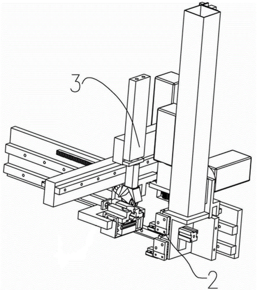
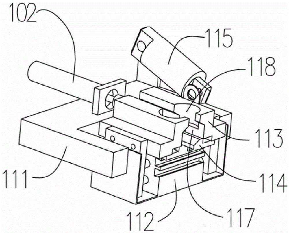
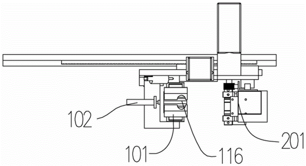
[0028] Embodiment 1: When the conventional straight joint 4 is transferred and processed, the entire processing equipment includes the picking manipulator 3, the auxiliary manipulator and the product to the machine tool manipulator device 2 such as figure 1 with Figure 5 Shown. The first clamping cylinder 112 is pushed clockwise by the rotating cylinder 115 to rotate 90°, the pick-up manipulator 3 is loosened so that the joint 4 is put into the lateral clamping opening 117 and the product entering the end gap, the rotating cylinder 115 is reversed The hour hand is pushed and rotated by 90°, and the product is sent to the manipulator device 2 of the machine tool through the laterally moving base 111. The laterally pushing air rod 102 pushes the connector 4 slowly forward from the product entry gap of the lateral clamp 117. The connector The position is slowly corrected due to the change of the gap, and finally the product is pushed into the fixture in the manipulator device 2 of...

Embodiment 2

[0029] Embodiment 2: When transferring the angle-pass joint 4 for processing, the entire processing equipment includes the picking manipulator 3, the auxiliary manipulator and the product delivery to the machine tool manipulator device 2. The picking manipulator 3 moves downward to place the joint 4 in the first clamping opening 116 of the angle pass, and the left and right first clamping blocks 113 are slowly clamped so that the joint 4 is automatically corrected according to the position of the first clamping opening 116 , The clamping joint 4 moves forward to the manipulator device 2 where the product is sent to the machine tool through the lateral movement base 111, the left and right first clamping blocks 113 are loosened, and the lateral pushing air rod 102 clamps the joint 4 from the lateral direction. The rear end of the port 117 is pushed forward, and the manipulator device 2 sent to the machine tool clamps the joint 4, and then sent to the machine tool for processing. ...


PUM


Abstract

The invention discloses an auxiliary manipulator used between manipulators to transmit products and correct positions. The auxiliary manipulator used between manipulators to transmit products and correct positions comprises a transversal pushing air rod and a first movable pneumatic clamp, and the first pneumatic clamp comprises a first clamping block, a first clamping air cylinder, a rotating air cylinder and a transversal moving base. The first clamping block is provided with a left block and a right block which are respectively connected with a push rod of the first clamping air cylinder, the first clamping air cylinder is connected with the transversal moving base in rotating mode, the upper side of the first clamping air cylinder is provided with a base plate, and a first clamping opening is formed by the base plate, the first left clamping plate and the first right clamping block. The transversal pushing air cylinder is arranged on the transversal moving base, one end of the rotating air cylinder is connected with the transversal moving base in rotating mode, and the other end of the rotating air cylinder is connected with the first clamping air cylinder in rotating mode. The manipulator device can be suitable for clamping and state correction of regular straight type products and irregular-shaped products, improves accuracy of the products on manipulator clamps, and improves working efficiency.

Description

Technical field [0001] The invention relates to the field of manipulator equipment, in particular to an auxiliary manipulator used for product transfer and position correction between manipulators. Background technique [0002] The existing auxiliary manipulators used between manipulators can generally only be used to transmit straight conventional products (such as conventional straight joints, etc.), and some special-shaped structures (such as right-angle joints and three-way joints, etc.) cannot be transmitted. The functionality is not high. In addition, during use, the robot in the previous process may have the wrong product gripping position, resulting in the wrong product gripping position when the robot in the previous process is transferred to the auxiliary manipulator, causing transfer errors and reducing work efficiency. Summary of the invention [0003] (1) Technical problems to be solved [0004] The technical problem to be solved by the present invention is to propose...

Claims


Application Information

Patent Timeline
Patent Type & Authority Patents(China)
IPC IPC(8): B25J15/00B25J11/00
Inventor 胡斌杨国华
Owner 余姚汉卓力克管件有限公司
Why Eureka
Try Eureka