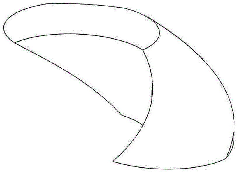
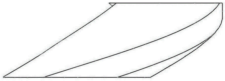
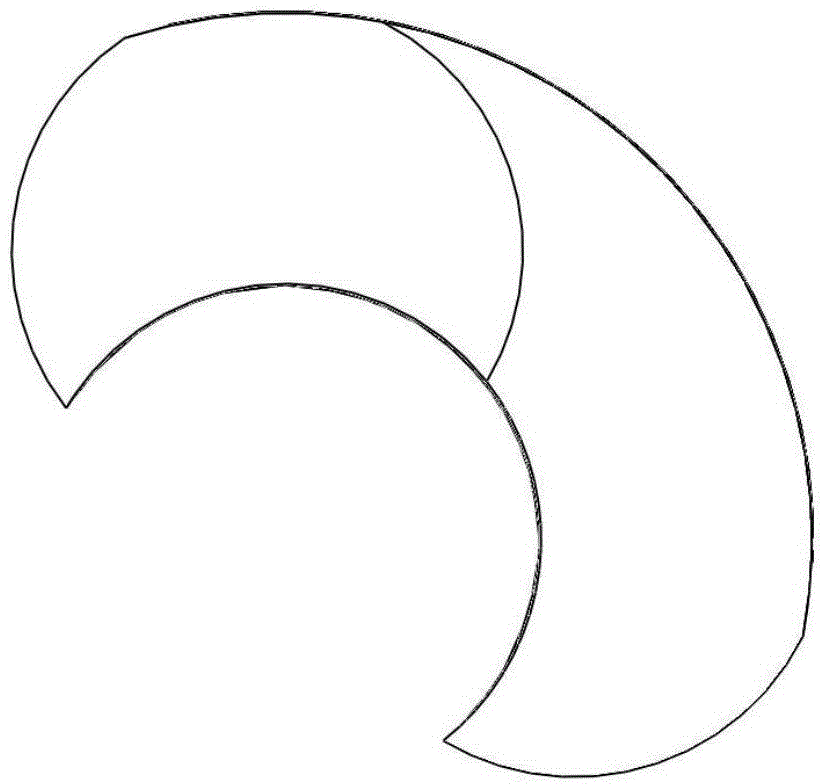
Screw rod type dry vacuum pump with combined screw rod rotor
A dry vacuum pump and combined technology, applied in the direction of rotary piston pump, pump, pump components, etc., can solve the problems of high production cost, complicated inspection and assembly, high defective rate, etc., to improve the yield and reduce the production cost. The degree of dependence, the effect of good cost performance
- Summary
- Abstract
- Description
- Claims
- Application Information
AI Technical Summary
Problems solved by technology
Method used
Image
Examples
Embodiment 1
[0109] Embodiment 1 (dry vacuum pump with equal-pitch hollow screw rotor shaft in the form of double-screw connection)
[0110] Such as Figure 17 , Figure 18 As shown, the dry vacuum pump includes a driving motor 6, a pump body and a combined screw rotor. There is an air suction port 1 on the pump body, and an exhaust port 5 on the coupling frame 10. One end of the pump body is fixedly connected to the left end The other end of the cover 28 is firmly connected to one end of the coupling frame 10, and the other end of the coupling frame 10 is fixedly connected to the bearing housing 8 and the connecting end plate 7 in turn; the combined screw rotor includes the active screw rotor and the driven screw rotor. The two ends are rotated and installed on the pump body through bearings 21 respectively. One end of the driving screw rotor is connected to the output shaft of the driving motor 6 through the coupling assembly 11. The driving screw rotor and the driven screw rotor are co...
Embodiment 2
[0112] Embodiment 2 (dry vacuum pump with variable-pitch hollow screw rotor shaft in the form of double-screw connection)
[0113] The difference between this embodiment and Embodiment 1 is that both the active screw rotor and the driven screw rotor are connected by a plurality of variable-pitch hollow screw-type rotor pieces 37 and the central shaft 36, and the active screw rotor and the driven screw rotor are connected by hollow screw rotors. The pitch of the rotor blades decreases sequentially along the airflow direction.
[0114] Active screw rotor such as Figure 19A As shown, it is a left-handed combined rotor shaft 24, and the driven screw rotor is as follows Figure 19B As shown, it is a right-handed combined rotor shaft 25; the two rotor shafts are formed by connecting a plurality of hollow screw rotor blades 37 with a helix angle of 180° and a central shaft 36 with variable pitch, and each rotor shaft is formed by a screw with two ends. Composition, the hollow scre...
Embodiment 3
[0116] Embodiment 3 (a dry vacuum pump with an equal-pitch hollow screw rotor shaft in the form of a screw passing through the through hole of the central shaft and bolted connections at both ends)
[0117] The difference between this embodiment and Embodiment 1 is that the central shaft 36 is evenly distributed with a plurality of connecting holes 13 in the axial direction, each connecting hole 13 is a radial through hole, and a hollow positioning hole is installed in each connecting hole 13. Pin 4, each hollow positioning pin 4 is inserted with a threaded screw 3 at both ends, and both ends of the screw 3 are fixed with hollow screw rotor pieces 37 through fastening bolts and lock washers 2 .
[0118] Active screw rotor such as Figure 25B As shown, it is a left-handed combined rotor shaft 24, and the driven screw rotor is as follows Figure 25AAs shown, it is a right-handed combined rotor shaft 25; the two rotor shafts are formed by connecting a plurality of hollow screw r...
PUM
 Abstract
Description
Claims
Application Information
 - R&D
- Intellectual Property
- Life Sciences
- Materials
- Tech Scout
- Unparalleled Data Quality
- Higher Quality Content
- 60% Fewer Hallucinations
Browse by: Latest US Patents, China's latest patents, Technical Efficacy Thesaurus, Application Domain, Technology Topic, Popular Technical Reports.
© 2025 PatSnap. All rights reserved.Legal|Privacy policy|Modern Slavery Act Transparency Statement|Sitemap|About US| Contact US: help@patsnap.com


