Heat energy floor

A floor and heat energy technology, applied in the field of floor heating, can solve problems such as high cost, poor floor pressure resistance, floor power failure, etc., and achieve the effects of high electric-heat conversion rate, strong pressure resistance, and strong pressure resistance.

Active Publication Date: 2013-04-24
苏州卡尔玛智能暖居科技有限公司
View PDF4 Cites 14 Cited by
  • Summary
  • Abstract
  • Description
  • Claims
  • Application Information

AI Technical Summary

Problems solved by technology

However, during use, if the electric heating material or metal parts on any one or more boards are damaged, all the installed floors will be powered off, and it is difficult to check which board has a problem, so It will inevitably lead to poor practicability and cause great difficulties for users.
Secondly, even if the problematic board is detected and replaced, because the electric heating material is embedded in the board and the metal parts are fixedly installed, the entire problematic board must be replaced, which is quite expensive and troublesome. Can not meet the needs of ordinary users
In addition, the safety of the electric heating materials or devices used in the floor in the prior art is not good enough, and it is difficult for the floor used in the home to avoid contact with water, which is obviously very dangerous
In addition, it is also known to introduce electric heating materials by slotting in the middle of the floor, but the floor’s pressure resistance is poor after slotting in the middle of the floor, and deformation will occur when it is used for a long time or when it encounters a slightly heavy load

Method used


Image

  • Heat energy floor

Examples


Embodiment Construction

[0014] The preferred embodiments of the present invention will be described in detail below in conjunction with the accompanying drawings, so that the advantages and features of the present invention can be more easily understood by those skilled in the art, so as to define the protection scope of the present invention more clearly.

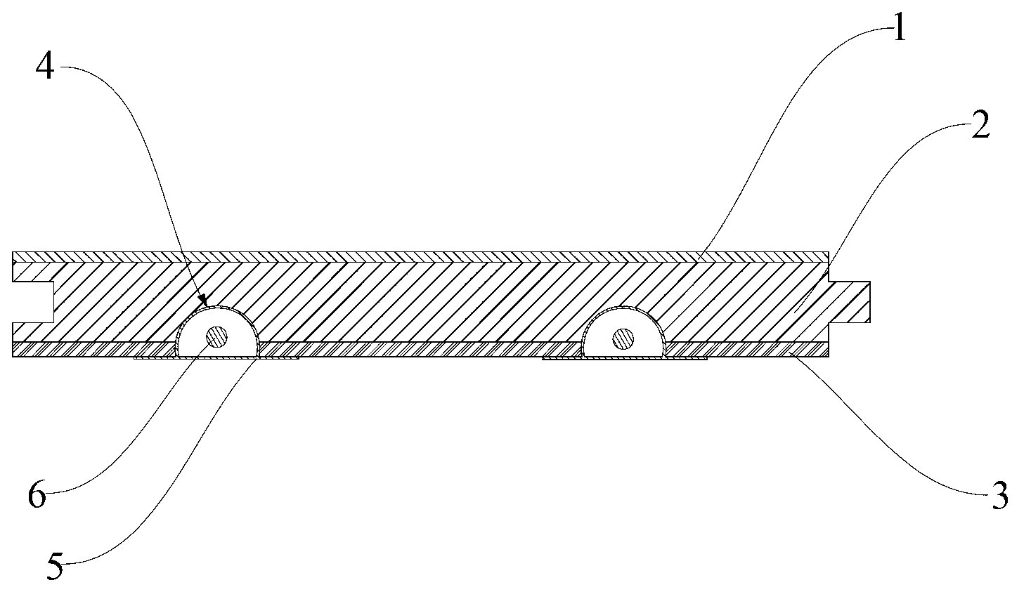
[0015] refer to figure 1 , this figure illustrates an embodiment of the thermal energy floor according to the present invention, which includes an upper layer 1, a bottom layer 3, and an intermediate layer 2 glued between the upper layer 1 and the bottom layer 3, and the bottom of the floor is formed along its length direction. Two cable troughs 4, two cable troughs 4 are arranged along the width direction of the board, the longitudinal section of the cable trough 4 is arc-shaped, and the metal material heat conducting frame 5 is arranged in the cable trough 4, and the metal material heat conducting frame 5 includes The longitudinal section ...


PUM


Abstract

The invention provides a heat energy floor. At least one winding displacement groove is arranged at the bottom of a floor along the length direction; the winding displacement groove is internally provided with a metal material heat-conducting frame; the metal material heat-conducting frame comprises an arc-shaped arch-shaped bracket with a vertical section which is chord-shaped and is located below, and a supporting plate located below the arch-shaped bracket; an opening is arranged at the position below the arch-shaped bracket, which corresponds to a chord on the arc-shaped section; the supporting plate covers the opening; a hollow cavity with two open ends is formed by the arch-shaped bracket and the supporting plate; the outer surface of the arch-shaped bracket at least has several parts which are respectively contacted with the surface of the inner wall of the winding displacement groove; at least one winding displacement groove is internally further provided with an electric heating wire; and the electric heating wire penetrates through the hollow cavity of the metal material heat-conducting frame and is electrically connected with a power supply. The heat energy floor disclosed by the invention has the advantages of strong anti-pressure ability, good heating effect, convenience in machining, and simple structure, is applicable to various fields, and has a very good application prospect.

Description

technical field [0001] The invention relates to the field of floor heating, and more particularly relates to a heat energy floor. Background technique [0002] It is well known that people have done extensive research on floor heating. Generally speaking, the electric heating material is arranged in the floor, and the purpose of heating is achieved by energizing the electric heating material in the floor, so that the floor generates heat for heating. This kind of floor is also equipped with conductive metal parts. During the installation process, two adjacent floors are connected through metal parts, so as to achieve the purpose of power supply and heating for the entire space. However, during use, if the electric heating material or metal parts on any one or more boards are damaged, all the installed floors will be powered off, and it is difficult to check which board has a problem, so Just inevitably cause practicability not strong, cause great difficulty to the user. S...

Claims


Application Information

Patent Timeline
Patent Type & Authority Applications(China)
IPC IPC(8): F24D13/02F24D19/00E04F15/02
Inventor 吴传明
Owner 苏州卡尔玛智能暖居科技有限公司
Why Eureka
Try Eureka