Liquid storage structure of rotary compressor

A rotary compressor and liquid storage structure technology, applied in the field of rotary compressors, can solve the problems of high cost, increased noise, and increased installation volume of rotary compressors, to reduce noise and vibration, reduce suction overheating, and simple structure reasonable effect

Active Publication Date: 2016-12-14
GUANGDONG MEIZHI COMPRESSOR
View PDF6 Cites 0 Cited by
  • Summary
  • Abstract
  • Description
  • Claims
  • Application Information

AI Technical Summary

Problems solved by technology

In this rotary compressor, since the accumulator is arranged outside the casing, the installation volume of the rotary compressor increases, and noise and cost due to the accumulator increase.

Method used


Image

  • Liquid storage structure of rotary compressor
  • Liquid storage structure of rotary compressor
  • Liquid storage structure of rotary compressor

Examples


Embodiment 1

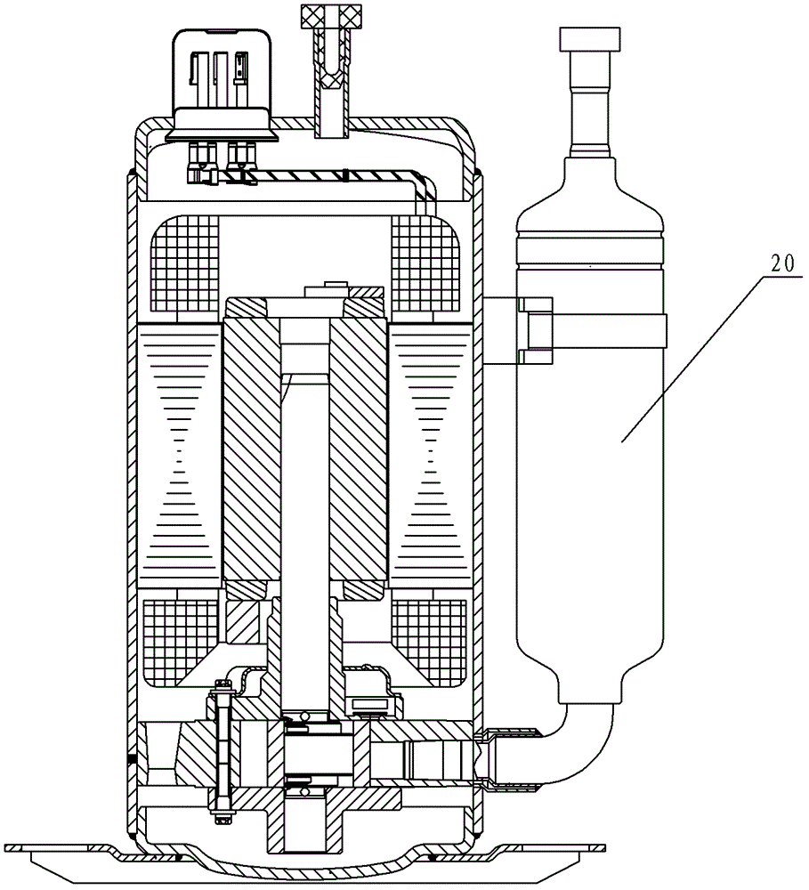
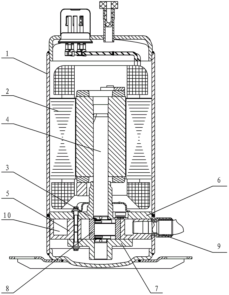
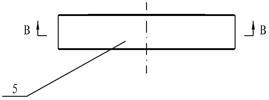
[0026] see Figure 2-Figure 7 , the liquid storage structure of the rotary compressor, the housing 1 of the compressor is provided with a motor 2 and a compression mechanism 3, the motor 2 is connected to the crankshaft 4 in the compression mechanism 3, the compression mechanism 3 includes a cylinder 5, and is housed in the cylinder 5 The piston 8 inside, the crankshaft 4 driven by the eccentric shaft to rotate eccentrically, the main bearing 6 and the auxiliary bearing 7 supporting the crankshaft 4, the main bearing 6 and the auxiliary bearing 7 are arranged on the cylinder 5, and the end face of the piston 8 is in contact with the main bearing 6. The end surfaces of the auxiliary bearing 7 located in the cylinder 5 are in gap contact and slide relative to each other. The cylinder 5 is provided with a slide groove 5.3 and a suction pipe installation hole 5.1 for installing the suction pipe 9 .

[0027] The cylinder 5 is provided with a liquid storage chamber 10, one end of th...

Embodiment 2

[0031] see Figure 8 , in this embodiment, the liquid storage chamber 10 is formed by sealing the through groove provided on the cylinder 5 and the widened flange end faces of the main bearing 6 and the auxiliary bearing 7 together.

[0032] See embodiment 1 for all the other undescribed parts, and will not repeat.

Embodiment 3

[0034] see Figure 9 , in this embodiment, the liquid storage chamber 10 is formed by sealing together the sinking groove provided on the cylinder 5 and the widened flange end surface on the auxiliary bearing 7 .

[0035] See embodiment 1 for all the other undescribed parts, and will not repeat.


PUM


Abstract

A liquid storage structure for a rotary compressor. A motor and a compression mechanism are arranged in the casing of the compressor. The motor is connected to the crankshaft in the compression mechanism. The compression mechanism includes a cylinder, a piston accommodated in the cylinder, and an eccentric shaft to drive the piston as The crankshaft that rotates eccentrically and the main bearing and auxiliary bearing supporting the crankshaft, the main bearing and the auxiliary bearing are arranged on the cylinder, the sliding vane groove and the suction pipe installation hole for installing the suction pipe are arranged on the cylinder, and the liquid storage is arranged in the compression mechanism The liquid storage chamber is composed of one, two or three of the cylinder, the main bearing and the auxiliary bearing. One end of the liquid storage chamber communicates with the suction pipe, and the other end of the liquid storage chamber communicates with the air inlet of the cylinder of the compression mechanism. ;The suction pipe mounting hole and the cylinder air inlet are located on the same side of the slide groove. The invention has the characteristics of simple and reasonable structure, small volume of the whole machine, can effectively reduce suction superheat, realize gas-liquid separation, and reduce suction superheat.

Description

technical field [0001] The invention relates to a rotary compressor, in particular to a liquid storage structure of the rotary compressor. Background technique [0002] The existing housing is a high-pressure rotary compressor, see attached figure 1 , in order to prevent liquid compression, need to be equipped with a liquid reservoir 20. Generally speaking, the accumulator should be arranged on the outer side of the rotary compressor and connected to the suction pipe of the rotary compressor. In this rotary compressor, since the accumulator is disposed outside the housing, the installation volume of the rotary compressor increases, and noise and cost due to the accumulator increase. Contents of the invention [0003] The purpose of the present invention is to provide a device with simple and reasonable structure, small overall volume, flexible operation, which can not only effectively reduce suction superheat, but also realize gas-liquid separation, reduce suction superh...

Claims


Application Information

Patent Timeline
Patent Type & Authority Patents(China)
IPC IPC(8): F25B43/00
Inventor 曹小军高强李华明
Owner GUANGDONG MEIZHI COMPRESSOR
Why Eureka
Try Eureka