Device simulating carbon dioxide (CO2) pipeline transport and leakage

A CO2 and pipeline technology, applied in the environmental field, can solve problems such as inability to analyze pipeline leakage

Inactive Publication Date: 2013-04-24
UNIV OF SCI & TECH OF CHINA
View PDF5 Cites 13 Cited by
  • Summary
  • Abstract
  • Description
  • Claims
  • Application Information

AI Technical Summary

Problems solved by technology

[0003] Currently researching CO 2 Leakage mechanism during pipeline transport using simulated CO 2 Leaky devices can only study static supercritical CO 2 The impingement behavior of transient jets through fine micro-holes and certain restricted jets (onto a flat plate placed perpendicular to the direction of the jet) cannot analyze the initial flow state of CO in the pipeline. 2 Leakage situation

Method used


Image

  • Device simulating carbon dioxide (CO2) pipeline transport and leakage
  • Device simulating carbon dioxide (CO2) pipeline transport and leakage
  • Device simulating carbon dioxide (CO2) pipeline transport and leakage

Examples


Embodiment Construction

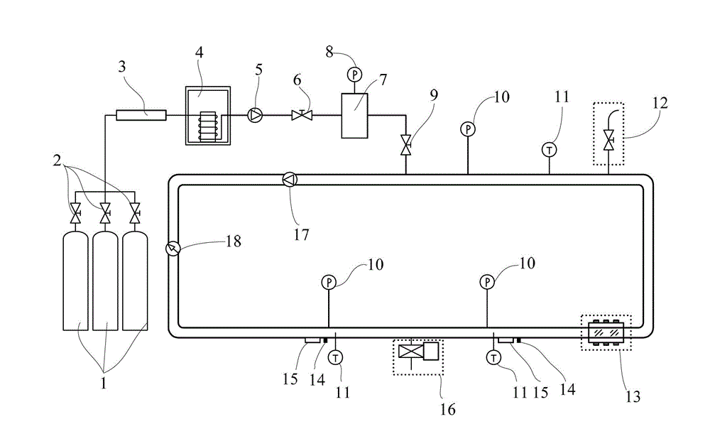
[0033] The object of the present invention is to provide a kind of simulated CO2 Pipeline transportation and leakage device, the simulated CO 2 The structural design of the leakage device can effectively solve the problem of CO under the flow state that cannot be truly reflected before. 2 Problems with leaking pipes inside and out.

[0034] The following will clearly and completely describe the technical solutions in the embodiments of the present invention with reference to the accompanying drawings in the embodiments of the present invention. Obviously, the described embodiments are only some, not all, embodiments of the present invention. Based on the embodiments of the present invention, all other embodiments obtained by persons of ordinary skill in the art without making creative efforts belong to the protection scope of the present invention.

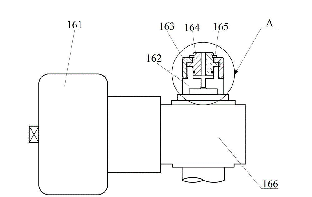
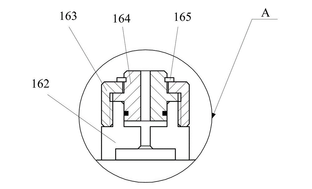
[0035] see Figure 1-Figure 7 , figure 1 The simulated CO provided for the embodiment of the present invention 2 Schematic d...


PUM


Abstract

The invention discloses a device simulating carbon dioxide (CO2) pipeline transport and leakage. The device simulating carbon dioxide (CO2) pipeline transport and leakage comprises a CO2 circulating pipeline, an air supplying bottle, a heating belt and a leakage nozzle. The air supplying bottle is communicated with the CO2 circulating pipeline through a valve. The air supplying bottle winds on the heating belt on the CO2 circulating pipeline and is arranged on a pipeline wall of the CO2 circulating pipeline and is communicated with an opening and closing leakage nozzle of the inner portion. A circulating pump and a pore plate flow meter are in series connection on the CO2 circulating pipeline. The circulating pump and a pore plate flow meter are connected with an air exhaust valve. A pressure sensor used for monitoring the inner portion pressure of the CO2circulating pipeline and a temperature sensor used for monitoring the inner portion temperature of the CO2 circulating pipeline are further arranged on the CO2 circulating pipeline. According to the device simulating carbon dioxide (CO2) pipeline transport and leakage, leakage condition of flowing state in the pipeline can be simulated.

Description

technical field [0001] The invention relates to the field of environmental technology, more specifically, to a simulated CO 2 Devices for pipeline transportation and leakage. Background technique [0002] CO 2 It is one of the typical greenhouse gases, and the CO emitted from factories such as coal power plants, thermal power plants or steel plants 2 After being captured, it is transported to the landfill site and permanently buried underground, which is the best way to realize CO 2 One of the feasible solutions for emission reduction, which can delay the global climate change brought about by the greenhouse effect and protect the earth's environment. In addition, CO 2 It is also a displacement medium for secondary or tertiary recovery of oilfields, so CO 2 Transported to oil wells, it is beneficial to enhance oil recovery. Either the CO 2 transported to a landfill site for landfill, or transported to an oil field, requires the removal of CO 2 It is transported to th...

Claims


Application Information

Patent Timeline
Patent Type & Authority Applications(China)
IPC IPC(8): G01M9/08
Inventor 谢启源涂然周学进李康姜羲
Owner UNIV OF SCI & TECH OF CHINA
Why Eureka
Try Eureka