

Loading device for template supporting systems
A technology of loading device and template support, applied in measuring device, using stable tension/pressure test material strength, instrument and other directions, can solve the problems of insufficient performance research, unclear product performance, difficult to guarantee safety, etc. The effect of operation, low production cost and convenient collection
- Summary
- Abstract
- Description
- Claims
- Application Information
AI Technical Summary
Problems solved by technology
Method used
Image

Examples
Embodiment 1
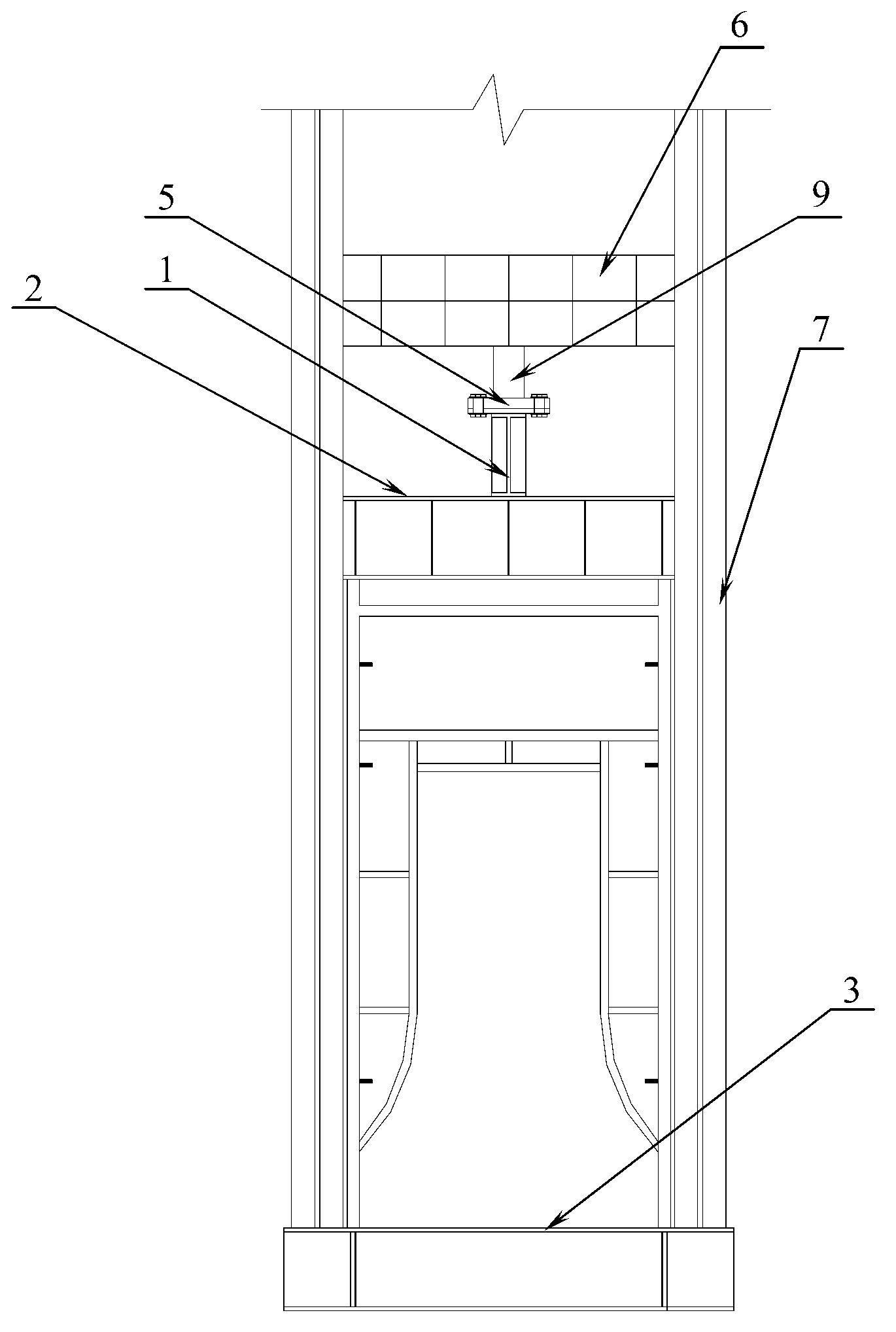
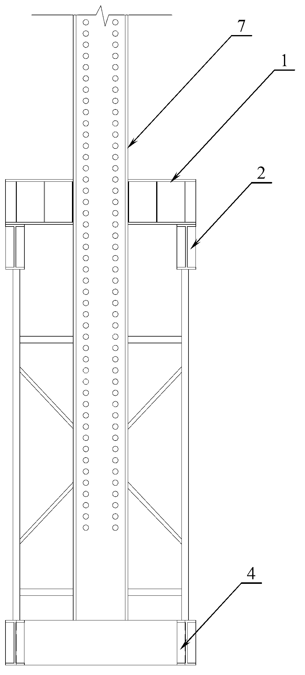
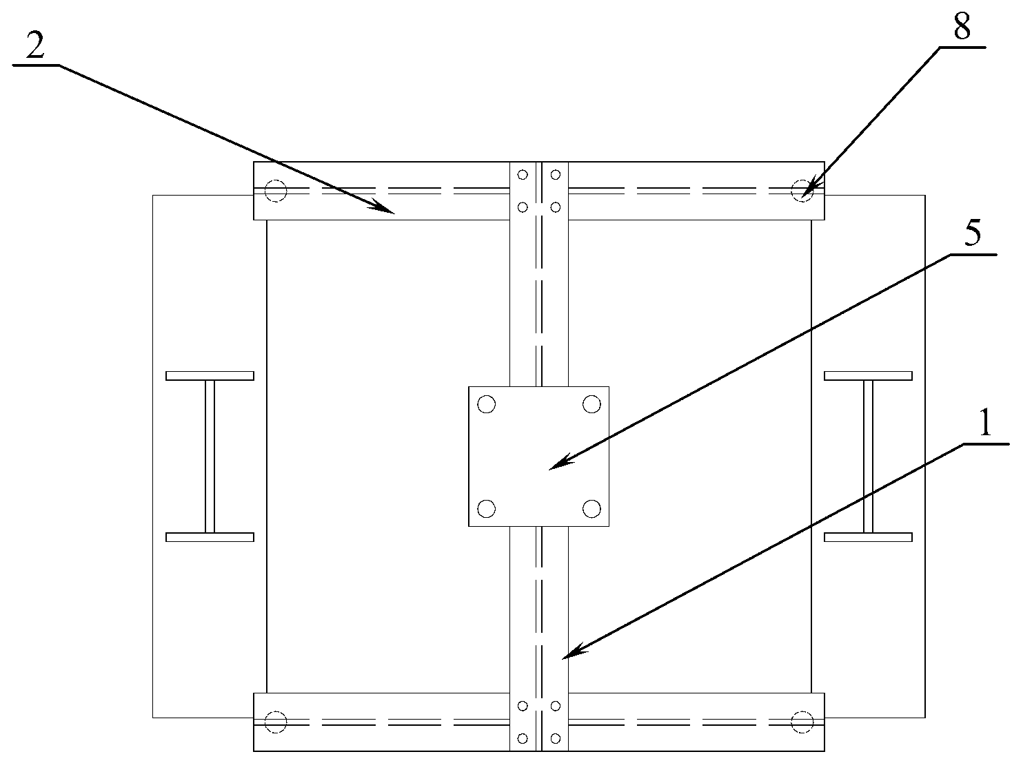
[0020] Example 1, such as figure 1 As shown in -4, the present embodiment discloses a loading device for a formwork support system, which includes a horizontal bottom beam 3 and a longitudinal bottom beam 4 welded together to form a square shape, and is welded and fixed on the horizontal bottom beam and the longitudinal bottom beam. The two symmetrical loading frames 7 are connected with a reaction beam 6 at the top of the two loading frames, and a loading device 9 is connected under the reaction beam, and the loading device is an actuator or a jack. The loading equipment is connected with the force transmission beam 1, specifically, a steel plate 5 matching the size of the action surface of the loading equipment is welded on the upper flange of the force transmission beam, the loading equipment is connected with the steel plate bolts, and the force transmission beam Both ends of the lower flange are respectively connected with the upper flange of a distribution beam 2 . The ...
PUM
 Abstract
Description
Claims
Application Information