Test system and test method for electrical properties of memristor component unit
A technology for testing systems and electrical characteristics, applied in the direction of instruments, measuring electronics, measuring devices, etc., can solve the problems of measurement accuracy to be further improved, single test method, no test method, etc., to ensure consistency and accuracy, and overall structure Compact, highly automated results
- Summary
- Abstract
- Description
- Claims
- Application Information
AI Technical Summary
Problems solved by technology
Method used
Image
Examples
Embodiment 1
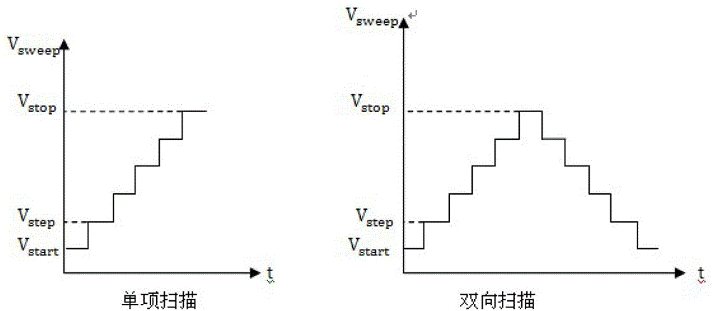
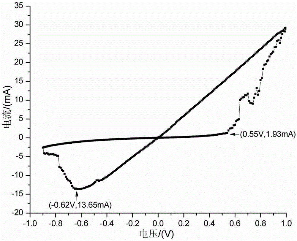
[0052] Since the DC I-V characteristic can intuitively reflect the overall electrical characteristics of the memristor, it is usually used as the first test step in the testing process. In this embodiment, the central control unit controls the source measurement unit to generate a voltage signal with increasing amplitude to measure the current corresponding to the memristor at this time through the test instruction. The voltage test range is -0.9V-0.9V, and the step of voltage increase The input value is 0.05V, the scanning mode is bidirectional scanning, and the current-voltage curve can be obtained by recording the corresponding voltage and current values (such as Figure 2b shown). Through this test curve, the threshold voltage / current characteristics and resistance switching characteristics of the memristor device unit can be studied. Depend on Figure 2b It can be seen that the threshold voltage for resistance change of the memristor is 0.55V / -0.62V, and the high and ...
Embodiment 2
[0054] In this embodiment, the central control unit sends corresponding test instructions, and the DC I-V characteristic test in Embodiment 1 is changed to a multi-impedance state characteristic test under the pulse action of a memristor. The specific test parameters are as follows: positive and negative pulses The numbers are respectively set to 5 / 5, the pulse width is 1us / 800ns, the amplitude is 0.7V / -0.6V respectively, the rest are the same as in Example 1, and the corresponding pulse times and resistance values are recorded to obtain the memristor device unit The multi-resistance characteristic curve (such as Figure 4 shown). Depend on Figure 4 It can be seen that under the action of a positive pulse, the resistance value of the memristor decreases from 10KΩ to 4KΩ in turn; under the action of a negative pulse, the resistance value returns from 4KΩ to 10KΩ, and there are multiple resistance state.
Embodiment 3
[0056] In this embodiment, the central control unit sends corresponding test instructions, and the DC I-V characteristic test in Embodiment 1 is changed to the resistance state switching rate and switching amplitude test of the memristor. The specific test parameters are as follows: the pulse amplitude It is set to 1V, the pulse width is increased from 2ns to 70ns in turn, and the step is 2ns, and the rest are the same as in Embodiment 1. Record the corresponding pulse width and resistance value to obtain the resistance state switching rate curve of the memristor device unit (such as Figure 5 shown); the pulse width is set to 1us, the pulse amplitude is sequentially increased from 400mV to 1V, and the step is 20mv, and the rest are the same as in Example 1. Record the corresponding pulse amplitude and resistance value to obtain the resistance of the memristor device State switching amplitude curve (such as Image 6 shown). Depend on Figure 5 It can be seen that under the p...
PUM
| Property | Measurement | Unit |
|---|---|---|
| Pulse width | aaaaa | aaaaa |
Abstract
Description
Claims
Application Information
 - R&D
- Intellectual Property
- Life Sciences
- Materials
- Tech Scout
- Unparalleled Data Quality
- Higher Quality Content
- 60% Fewer Hallucinations
Browse by: Latest US Patents, China's latest patents, Technical Efficacy Thesaurus, Application Domain, Technology Topic, Popular Technical Reports.
© 2025 PatSnap. All rights reserved.Legal|Privacy policy|Modern Slavery Act Transparency Statement|Sitemap|About US| Contact US: help@patsnap.com


