Control device and control method
A technology for controlling equipment and processing equipment, which is applied in the direction of multi-programming devices, data processing power supplies, program startup/switching, etc., and can solve problems such as waste of power consumption
- Summary
- Abstract
- Description
- Claims
- Application Information
AI Technical Summary
Problems solved by technology
Method used
Image
Examples
Embodiment approach
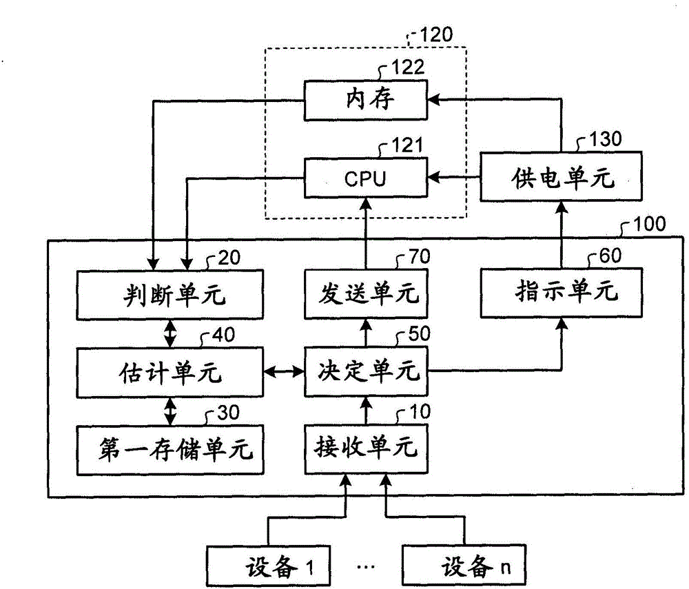
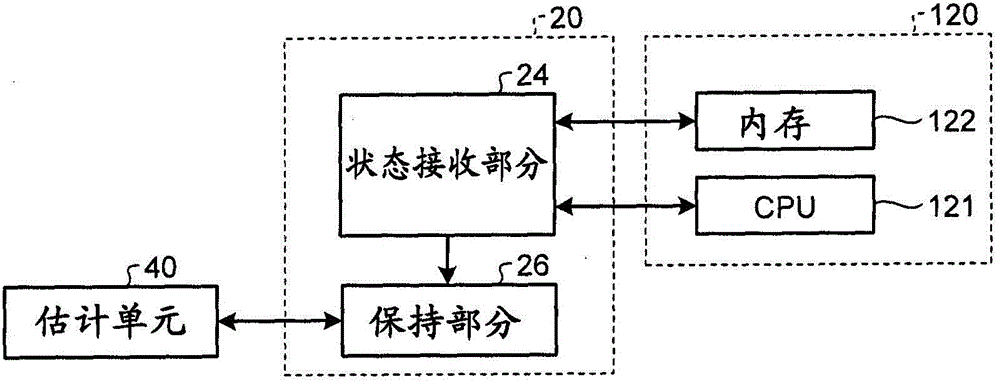
[0028] According to an embodiment, the control device includes a receiving unit, a judging unit, an estimating unit, a deciding unit, an indicating unit and a sending unit. The receiving unit is configured to receive an interrupt request requesting a processing device including a plurality of elements capable of individually undergoing voltage control to perform interrupt processing. The judging unit is configured to judge the state of each element. The estimating unit is configured to estimate, for each element, an activation time representing a time required for the element to become an operation mode representing an operable state after power is supplied, based on a determination result of the determination unit. The decision unit is configured to decide a time start representing a timing at which power supply is to be started for each element based on a difference in start-up time between the elements. The instructing unit is configured to instruct the power supply unit f...
no. 1 approach
[0030] figure 1 is a block diagram illustrating an example of a schematic configuration of the control device 100 according to the first embodiment. The control device 100 receives an interrupt request requesting the processing device 120 to perform interrupt processing from each of the plurality of devices 1 to n, and transmits the received interrupt request to the processing device 120 . The devices are devices each having at least one of a function of inputting data from the outside to the processing device 120 and a function of outputting data from the processing device 120 to the outside, examples of which include a keyboard, HDD, network interface unit and timer. For example, processing device 120 may include a central processing unit (CPU) 121 and memory 122 .
[0031] In an idle state in which processing is not performed, the processing device 120 according to this embodiment becomes a power saving state (sleep state) in which power supply to a plurality of elements ...
no. 2 approach
[0050] Next, a second embodiment will be described. In the second embodiment, if the processing device 120 is in the active state (running state) in which the processing device 120 is executing processing, the control device 100 transmits the received interrupt request to the processing device 120, or, if the processing device 120 is in In the idle state where the processing device 120 does not perform any processing, the control device 100 sends the received interrupt request to the processing device 120 only when a predetermined condition is met. The specific details will be described below. The same parts as those of the first embodiment will be denoted by the same reference numerals, and description thereof will not be repeated as appropriate.
[0051] Figure 7 is a block diagram illustrating an example of the control device 100 according to the second embodiment. Such as Figure 7 As explained in , the difference between the control device 100 and the first embodimen...
PUM
 Abstract
Description
Claims
Application Information
 - R&D
- Intellectual Property
- Life Sciences
- Materials
- Tech Scout
- Unparalleled Data Quality
- Higher Quality Content
- 60% Fewer Hallucinations
Browse by: Latest US Patents, China's latest patents, Technical Efficacy Thesaurus, Application Domain, Technology Topic, Popular Technical Reports.
© 2025 PatSnap. All rights reserved.Legal|Privacy policy|Modern Slavery Act Transparency Statement|Sitemap|About US| Contact US: help@patsnap.com


