
Vacuum welding device and welding method for superconducting stack of high-temperature superconducting current lead

A current lead, high-temperature superconducting technology, applied in welding equipment, metal processing equipment, manufacturing tools, etc., can solve the problems of slow heating and cooling, and achieve the effect of solving virtual welding, shortening the solidification time of solder, and avoiding virtual welding.

Active Publication Date: 2013-05-01
INNOVA SUPERCONDUCTOR TECH
View PDF6 Cites 7 Cited by
  • Summary
  • Abstract
  • Description
  • Claims
  • Application Information

AI Technical Summary

Problems solved by technology

[0006] The present invention proposes another welding device and welding method for superconducting stacks used in vacuum welding current leads. Welding efficiency and quality of superconducting stacks

Method used


Image

  • Vacuum welding device and welding method for superconducting stack of high-temperature superconducting current lead
  • Vacuum welding device and welding method for superconducting stack of high-temperature superconducting current lead
  • Vacuum welding device and welding method for superconducting stack of high-temperature superconducting current lead

Examples


Embodiment 1

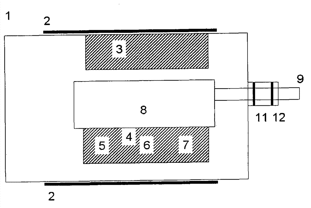
[0031] Such as figure 1As shown, a tubular vacuum chamber 1 is made of stainless steel, a heating belt 2 is wound on the outside, and a cold base 3 and a hot base 4 are respectively installed on the left and right sides of the inside. The cold base 3 is fixed with screws, and is closely attached to the inner wall of the vacuum chamber. A thin aluminum strip is placed in the middle to achieve good thermal contact. The material is aluminum. The thermal base 4 is also fixed with screws, but it is 1 cm away from the wall of the vacuum chamber to avoid thermal contact. At the same time, the part of the top of the fixing screw that contacts the thermal base is embedded with an epoxy resin gasket, so that the thermal base 4 does not directly contact the screw. Improve insulation conditions. A set of nickel-chromium alloy heating wires 5, 6, and 7 are respectively embedded in the inner head, middle, and tail of the thermal base 4, and are respectively connected to an external control...

Embodiment 2

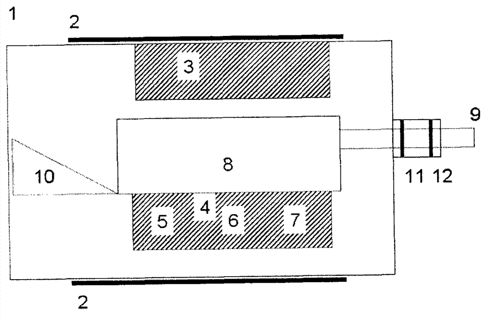
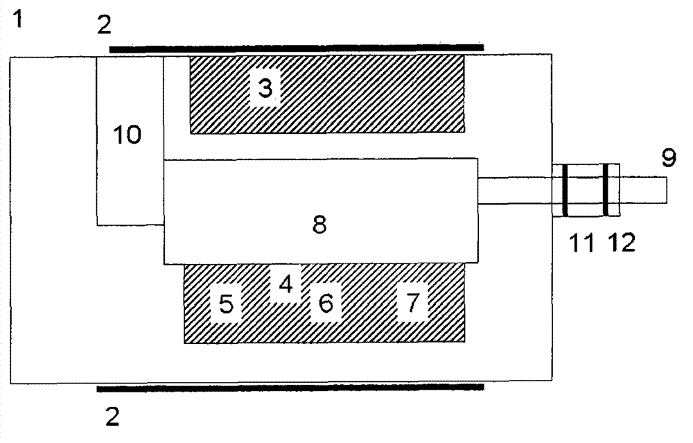
[0043] The difference between Embodiment 2 and Embodiment 1 is that the movable part is a rotating shaft 9 and is equipped with a rolling guide rail 10 . The using method of welding mold 8 is the same as embodiment 1. In the welding method, the temperature setting of the outer wall of the vacuum furnace 1 can be set at any value between 50-120°C. The setting value of the heating temperature of the thermal base 4 can exceed the melting point of the selected solder by 20-35°C.


PUM


Abstract

The invention discloses a vacuum welding device and a method for a high-temperature superconducting stack used for a large-sized magnet current lead. The vacuum welding device comprises an independent heating vacuum chamber, a cold base and a hot base, wherein the cold base and the hot base are arranged in the vacuum chamber. The interior of the vacuum chamber also comprises a movable welding die and a moving part which can be used for enabling the die to move in the vacuum chamber. After the welding die is contacted with the hot base through the moving part and heated to specified temperature, the welding die is separated from the hot base and is contacted with the cold base to realize rapid cooling. According to the vacuum welding device and the welding method, the superconducting stack is high in density, welding effect and current-carrying capability; and 7-stacked critical current measured under self-fields at 77K can reach 70 percent of the critical current of an original strip, and 4-stacked critical current exceeds the 80 percent critical current of the original strip. The superconducting stack can be applied to the large-sized magnet current lead as a discharge current conductor, and therefore, the effect of reducing heat emission and heat transfer of the lead is achieved, the cooling power is saved, and the operating environment of a magnet is improved.

Description

technical field [0001] The invention relates to a welding device and method for superconducting stacks of high temperature superconducting current leads of large superconducting magnets. Background technique [0002] Large magnets can be widely used in fields such as energy, medicine, national defense, and large scientific research, providing large-scale, high-intensity magnetic fields for medical magnetic resonance imaging, controllable nuclear fusion, and particle accelerators. High-temperature superconducting (HTS) current leads reduce lead heating and heat transfer losses, can improve magnet energy efficiency, and improve operating conditions. It is one of the frontiers of large-scale magnet technology development. According to comparative experiments, the large magnet used in the European Hadron Collider has a heat loss of 47W / kA when using conventional copper current leads, and 1.04W / kA when using liquid helium to cool the copper leads. The loss drops to 0.1W / kA. In ...

Claims


Application Information

Patent Timeline
Patent Type & Authority Applications(China)
IPC IPC(8): B23K1/008
Inventor 李晓航王素丽郭文胜
Owner INNOVA SUPERCONDUCTOR TECH
Learn More