Control system and control method of welding equipment

A technology of welding equipment and control system, which is applied in the field of welding equipment control system, can solve the problems such as the signal is easily interfered and affects the welding quality, and achieves the effect of stable welding, guaranteed welding, and enhanced anti-interference ability

Active Publication Date: 2013-05-01
PANASONIC WELDING SYST TANGSHAN
View PDF7 Cites 8 Cited by
  • Summary
  • Abstract
  • Description
  • Claims
  • Application Information

AI Technical Summary

Problems solved by technology

[0010] The purpose of this invention is to solve the problem in the prior art that the signal sent from the side of the wire feeding device to the side of the welding power source is easily disturbed, thereby affecting the welding quality, and provides a control system and control method for welding equipment

Method used


Image

  • Control system and control method of welding equipment
  • Control system and control method of welding equipment
  • Control system and control method of welding equipment

Examples


no. 1 example

[0033] Refer below Figure 2 to Figure 7 A first embodiment of the present invention is described.

[0034] [Hardware configuration]

[0035] First, the hardware configuration of the first embodiment of the present invention will be described.

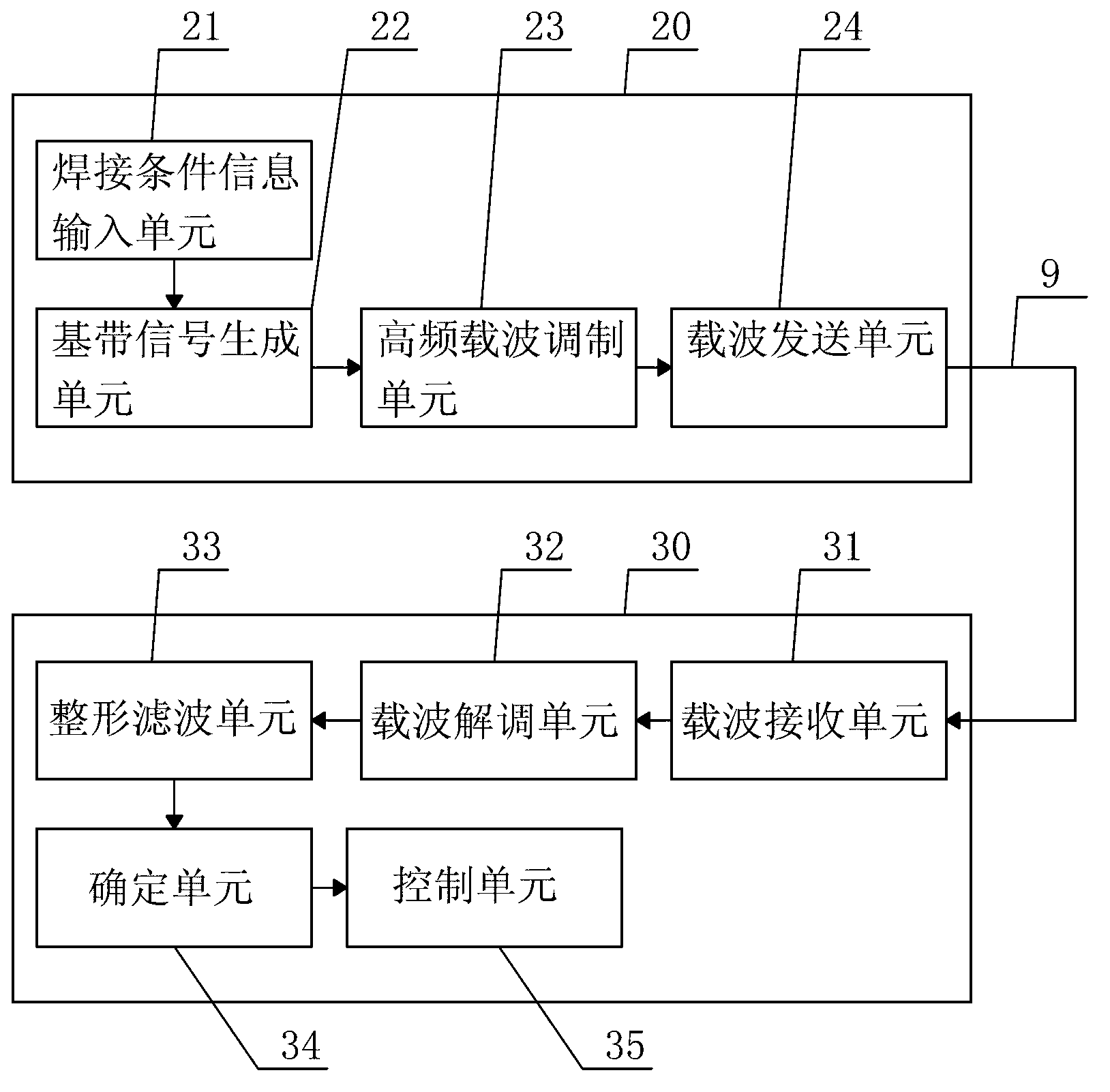
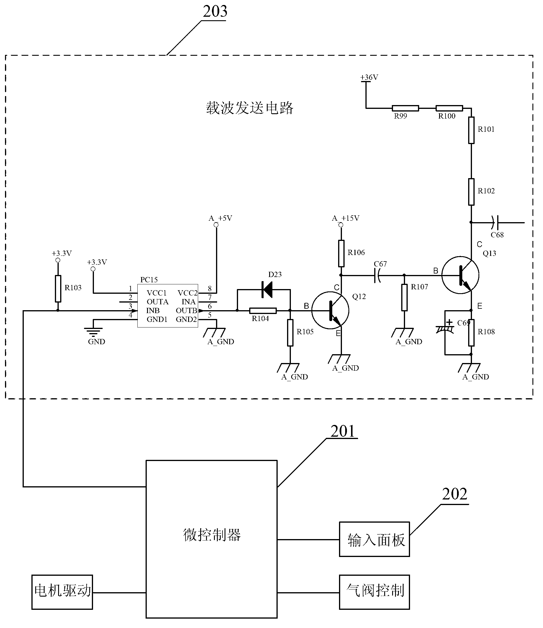
[0036] figure 2 It is a schematic diagram of the hardware structure of the control device 20 (hereinafter referred to as "first control device") of the wire feeding device according to the first embodiment of the present invention. As shown in the figure, the first control device 20 includes a microcontroller 201 (corresponding to the baseband signal generation unit 22 and a high-frequency carrier modulation unit 23), an input panel 202 (corresponding to the welding information input unit 21), and a carrier transmission circuit 203 ( Corresponding to the carrier sending unit 24). The microcontroller 201 is electrically connected to the input panel 202 (corresponding to the welding condition information input unit 21) and the carri...

no. 2 example

[0072] Refer below Figure 8 and Figure 9 A second embodiment of the present invention is described.

[0073] The second embodiment is basically the same as the first embodiment in terms of hardware configuration and working process, so the description thereof will not be repeated. Only the differences are described below. The difference between the second embodiment and the first embodiment is that the first control device still sends the welding condition information to the second control device when the welding device is in standby, except that the welding device is working. The welding equipment standby here means that the welding torch switch is not turned on. Figure 8 and Figure 5 Parts of the process are the same, so the same steps are given the same notation.

[0074] [Workflow when welding equipment is on standby]

[0075] Figure 8 It shows the working flow of the control system of the present invention in the standby state of the welding equipment. like ...

no. 3 example

[0083] Refer below Figure 10 A third embodiment of the present invention is described.

[0084] The third embodiment of the present invention has basically the same hardware configuration and work flow as the first embodiment, except that in the third embodiment, in the high-frequency carrier modulation step, the baseband signal is modulated into three high-frequency carrier waves , the corresponding carrier sending step, carrier receiving step, carrier demodulating step, shaping and filtering step and determining step all process the three-way signal.

[0085] Since there is no substantial difference in technology between generating, modulating, transmitting, and receiving two high-frequency carriers and three high-frequency carriers, no detailed description is given here. The following only describes the flow of the steps of determining the outputted three-way low-frequency modulation signals after shaping and filtering.

[0086] Figure 10 It is a specific flow chart of...


PUM


Abstract

The invention provides a control system and a control method of welding equipment. The welding equipment comprises a welding power source and a wire feeding device, wherein the communication is carried out between the welding power source and the wire feeding device by a method of loading high-frequency carriers on a power line. The control method comprises the following steps of inputting information of welding conditions at the wire feeding device side; generating a baseband signal according to the information of the welding conditions; demodulating multiple paths of high-frequency carriers with different frequency according to the generated baseband signal; sending the multiple paths of high-frequency carriers with different frequencies; at the welding power source side, receiving the multiple paths of high-frequency carriers with different frequency sent from the wire feeding device side; demodulating the received high-frequency carriers into a low-frequency modulation signal; shaping and filtering the demodulated low-frequency modulation signal, and outputting; and determining a signal for controlling the output of the welding power source, and controlling the output of the welding power source according to the determined signal. The control system and the control method have the advantages that the anti-jamming capability is realized, and the stable welding is ensured.

Description

[technical field] [0001] The invention relates to a control system and control method of welding equipment composed of a welding power supply and a wire feeding device, especially a control system and a control method for controlling the welding power supply by inputting welding information from the wire feeding device side. [Background technique] [0002] With the rapid development of the manufacturing industry, in the field of large-scale construction machinery, especially in shipbuilding, steel structure and other industries, welding equipment is widely used. Welding equipment generally consists of welding power supply and wire feeding device, and the two are connected by control cables. , during welding, the welding information is input from the wire feeding device to control the wire feeding speed, and the welding information is transmitted to the welding power source to control the output of the welding power source. [0003] Generally, the wire feeding device is conne...

Claims


Application Information

Patent Timeline
Patent Type & Authority Applications(China)
IPC IPC(8): B23K9/095B23K9/133
Inventor 李再兴安小东翟玉喜王帅袁钊
Owner PANASONIC WELDING SYST TANGSHAN
Why Eureka
Try Eureka