Automatic fluid modulation device for liquid injection forming mold

A liquid injection molding and mold technology, applied in the field of liquid injection molding mold automatic fluid modulation device, can solve the problems of modulation failure, low stability, difficult debugging, etc. Effect

Inactive Publication Date: 2015-05-27
XIAMEN UNIV OF TECH
View PDF4 Cites 0 Cited by
  • Summary
  • Abstract
  • Description
  • Claims
  • Application Information

AI Technical Summary

Problems solved by technology

[0007] For example, in the injection molding of thermoplastics, due to the uneven temperature caused by shear mutagenesis, the high-temperature fluid has low viscosity and fast flow rate under the same injection pressure, while the low-temperature fluid has high viscosity and slow flow rate. lead to uneven filling; for the reaction injection molding of thermosetting materials (such as liquid silicone rubber), due to the uneven temperature caused by shear mutagenesis, the fluid in the runner will be cured (vulcanized) to different degrees, and the high temperature fluid will be overheated. Vulcanization occurs early, the flow slows down, and the low-temperature material has a high flow rate, resulting in uneven filling of each product cavity
[0008] 2) Traffic is difficult to control and distribute
This makes mold design, processing and production debugging difficult.
[0010] For saving raw materials, improving product quality, and increasing production efficiency, hot runner modules (also known as hot half molds, for thermoplastics) and cold runner modules (also known as cold half molds, for thermosetting plastics) technologies , the above method has certain defects: First, because the hot half mold and cold half mold are expensive, in order to cope with the production of family products, it is necessary to order a set of corresponding hot half molds or cold half molds for a family product, which makes the mold cost Second, because the hot half mold and cold half mold technology generally use needle valves for pouring, the distance between the needle valves itself has a minimum value limit, and in order to ensure the balance of cavity filling of family products, each The distance between the needle valve and the main gate needs to be increased or decreased accordingly, which leads to a large mold volume, which also puts forward higher requirements for the performance parameters of the injection molding equipment
Third, it is difficult to realize the standardization of hot half mold or cold half mold
[0013] 1) Difficult to debug
[0014] Generally, the valve stem is manually rotated to the required position before use, and its positioning accuracy and repeat positioning accuracy are difficult to guarantee
[0015] 2) The stability is not high
[0016] After the valve stem rotates to a certain angle, it only depends on the static friction between it and the valve sleeve to maintain stability. During the production process, the valve stem will be impacted by the fluid flowing through the valve port and bear the torque exerted by the fluid on it. There is a possibility of deflection, causing the modulation to fail
[0017] 3) Restricted use
[0018] First, the cold runner injection molding process of thermoplastic materials needs to push out the runner condensate in each injection cycle, and the valve hole in the manual fluid adjustment part runs through the middle and upper part of the valve stem, so that the condensation in the valve hole However, the material cannot be ejected, which limits the device to only be used for hot runner injection molding of thermoplastic materials or cold runner injection molding of thermosetting materials, and cannot be used for cold runner injection molding of ordinary thermoplastic materials. In the cold runner injection molding process of ordinary thermoplastic materials, the temperature unevenness and filling imbalance caused by shear mutagenesis are the most serious
[0019] Second, even for hot-runner injection molding of thermoplastic materials or cold-runner injection molding of thermosetting materials, due to the inevitable condensation in the runners during the production process (especially for thermosetting materials), manual fluid Stem of modulating part is always in deflected position, making subsequent mold runner cleaning very difficult

Method used


Image

  • Automatic fluid modulation device for liquid injection forming mold
  • Automatic fluid modulation device for liquid injection forming mold
  • Automatic fluid modulation device for liquid injection forming mold

Examples


Embodiment 1

[0048] Example 1 is a hot runner injection molding process for thermoplastic materials and a cold runner injection molding process for thermosetting materials.

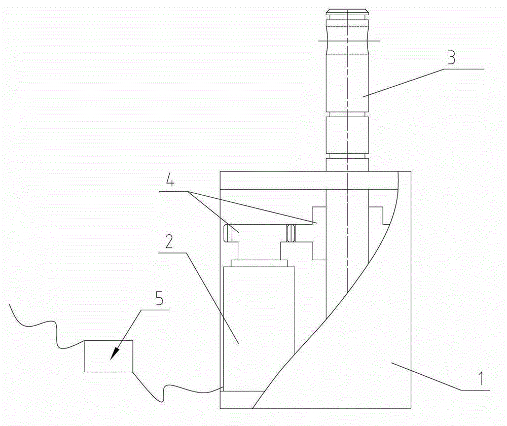
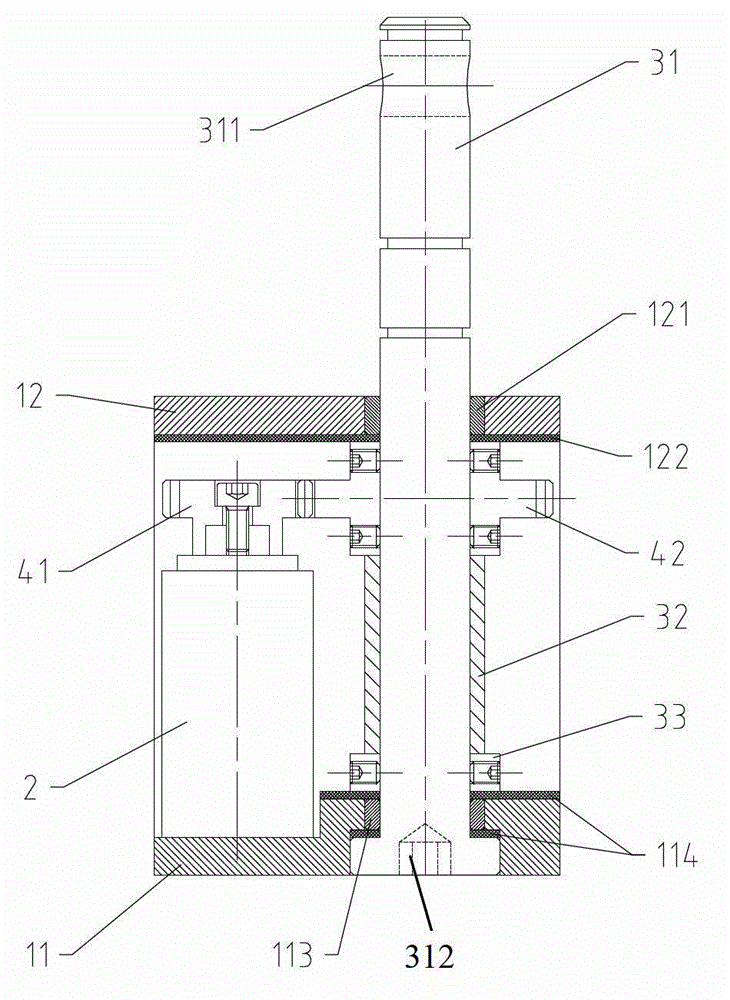
[0049] See Figure 1~3 , Example 1 is provided with a frame 1, a micro servo motor 2, a modulation valve 3, a reduction gear pair 4 and a controller 5. The micro servo motor 2 and the modulation valve 3 are fixed on the frame 1. The output end of the micro servo motor 2 is connected with the input gear 41 of the reduction gear pair 4, and the output gear 42 of the reduction gear pair 4 is set on the valve stem of the modulation valve 3. 31 on. The modulation valve 3 is provided with a valve stem 31, a sleeve 32 and a fixed retaining ring 33. The sleeve 32 and the fixed retaining ring 33 are sleeved on the lower part of the valve stem 31. The output terminal of the controller 5 is connected to the micro servo motor 2, and the input terminal of the controller 5 is connected to the sensor on the injection molding machine ...

Embodiment 2

[0068] See Figure 4 , Similar to embodiment 1, the difference is that the valve hole 311 at the upper end of the valve stem 31 in the embodiment 1 (see figure 2 ) Is changed to U-shaped groove 311' (it can also be other open valve ports with different fluid characteristics).

[0069] This embodiment 2 is suitable for the cold runner injection molding process of ordinary thermoplastic materials. The specific application and installation methods are as follows:

[0070] See Figure 5 This embodiment 2 is installed on the mold support plate P2 of the mold. During injection, the valve stem 31 rotates a certain angle to modulate the fluid. After the injection stage, the valve stem 31 rotates back, so as to avoid the flow channel condensation There is a weak link in the material (that is, the position where the valve port and the runner intersect), and the product and the gate condensate can be smoothly ejected by the thimble P1. Figure 5 In, mark P4 is the reset rod of the mold, and t...

Embodiment 3

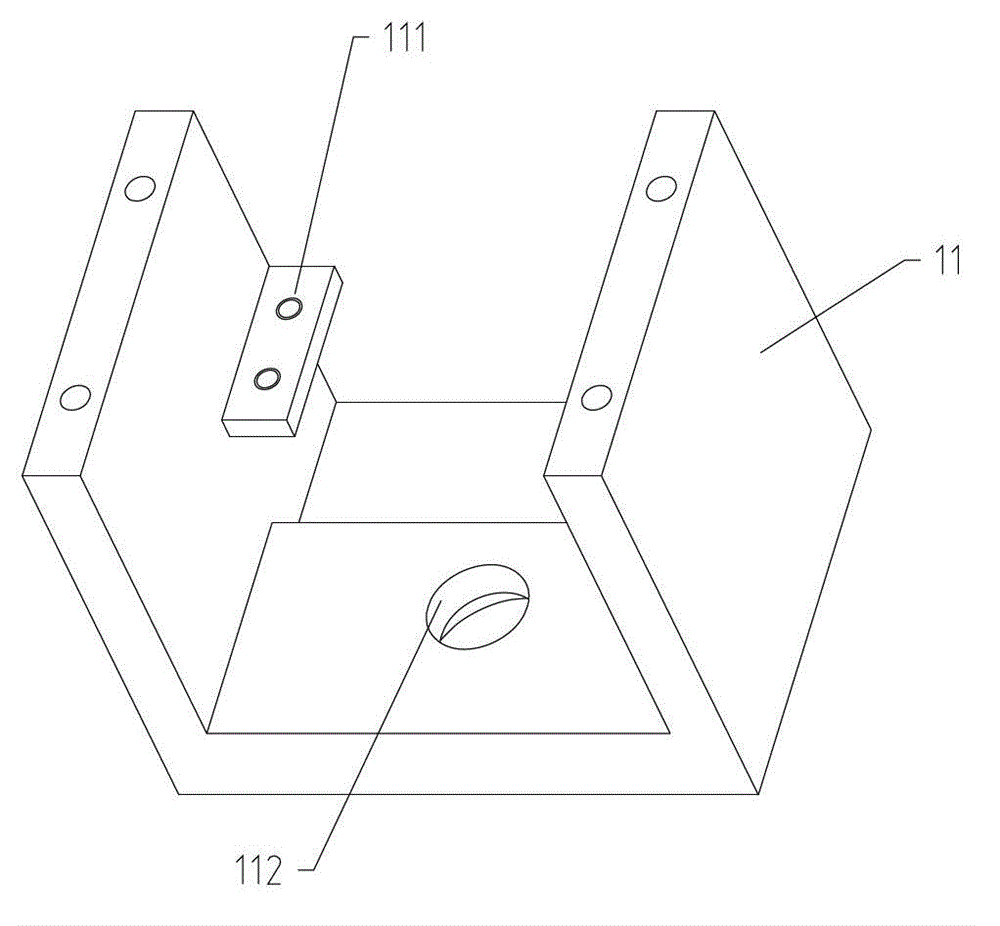
[0073] See Figure 7 with 8 Similar to Embodiment 1, the difference is that Embodiment 3 is suitable for occasions where the required torque is relatively large, and an upper miniature planar thrust ball bearing 123 and a lower miniature planar thrust ball bearing 115 are added to the valve stem 31. The miniature plane thrust ball bearing can effectively prevent the valve stem 31 from moving axially. The D-shaped limit flange at the bottom end of the valve stem 31 and its matching form with the countersunk limit hole 112 are as follows Picture 8 Shown. The rest mark with figure 2 correspond. The installation method and working process are the same as in Example 1.


PUM


Abstract

The invention discloses an automatic fluid modulation device for a liquid injection forming mold, and relates to a liquid injection forming mold. The automatic fluid modulation device is provided with a rack, a micro servomotor, a modulation valve, a reduction gear set and a controller, wherein the micro servomotor and the modulation valve are mounted on the rack; the micro servomotor is connected with the modulation valve through the reduction gear set; an output end of the controller is electrically connected with the micro servomotor; a driving shaft of the micro servomotor is connected with an input end gear of the reduction gear set; an output end gear of the reduction gear set is fixedly connected with a valve rod of the modulation valve; an input end of the controller is externally connected with a sensor on an injection forming machine; the modulation valve comprises the valve rod, a sleeve and a fixing check ring; the valve rod is rotationally matched with the rack; and the lower part of the valve rod is sleeved with the sleeve and the fixing check ring. The automatic fluid modulation device is compact in structure, easy to use, flexible in use pattern and wide in applicability; and the automatic fluid modulation is accurate, quick and stable.

Description

Technical field [0001] The invention relates to a liquid injection molding die, including a cold and hot runner injection molding die for thermoplastic materials and a cold runner injection molding die for thermosetting materials, and in particular to a fluid that acts on a die runner channel, and the fluid enters the mold cavity. An automatic fluid modulating device for liquid injection molding molds that can flow and promote fluid temperature balance. Background technique [0002] At present, in the liquid material injection molding process, in order to reduce production costs and improve production efficiency, the industry is increasingly using multi-cavity molds (Multi-cavity Mold), family molds (Family Mold) and stack molds (Stack Mold) As production equipment for product production. The characteristic of the process is that the liquid material in the production process no longer directly enters the product cavity, but is redirected through the flow channel and filled into ...

Claims


Application Information

Patent Timeline
Patent Type & Authority Patents(China)
IPC IPC(8): B29C45/77
Inventor 龚晓叁周水庭
Owner XIAMEN UNIV OF TECH
Why Eureka
Try Eureka