A control system and control method for controlling the reaction temperature of a cracking furnace

A technology of control system and control method, which is applied in general control system, control/regulation system, adaptive control, etc., can solve the problems of increased experiment time, unsatisfactory temperature control effect, strong coupling influence of cracking furnace temperature, etc., to achieve shortening Effect of experiment time, shortening temperature rise time and stabilization time

Active Publication Date: 2016-02-24
CHINA PETROLEUM & CHEM CORP +1
View PDF1 Cites 0 Cited by
  • Summary
  • Abstract
  • Description
  • Claims
  • Application Information

AI Technical Summary

Problems solved by technology

[0004] However, since the temperature control of the resistance furnace is characterized by large time constant, large inertia, and large pure hysteresis, and the temperature coupling of each section in the cracking furnace is strongly affected, the temperature fluctuates violently during the heating stage of the cracking furnace
However, if the temperature fluctuation range is reduced by slowly increasing the temperature setting value to a given temperature with a small slope, the experiment time will be greatly increased, and the temperature control effect is not ideal, and the temperature fluctuation still exists, such as figure 2 On the other hand, due to the composition and flow rate of raw materials will vary with different experimental requirements, resulting in poor ability of the control system to overcome interference when feeding in the heat preservation stage, excessive temperature fluctuations, and temperature control deviations It exceeds ±20°C and the stabilization time is too long, usually about 20-30 minutes depending on the raw material, which seriously affects the analytical quality of the raw material and causes waste of experimental raw materials, such as image 3 shown

Method used


Image

  • A control system and control method for controlling the reaction temperature of a cracking furnace
  • A control system and control method for controlling the reaction temperature of a cracking furnace
  • A control system and control method for controlling the reaction temperature of a cracking furnace

Examples


Embodiment Construction

[0023] The control system and control method for controlling the reaction temperature of the cracking furnace according to the present invention will be described in detail below in conjunction with the accompanying drawings.

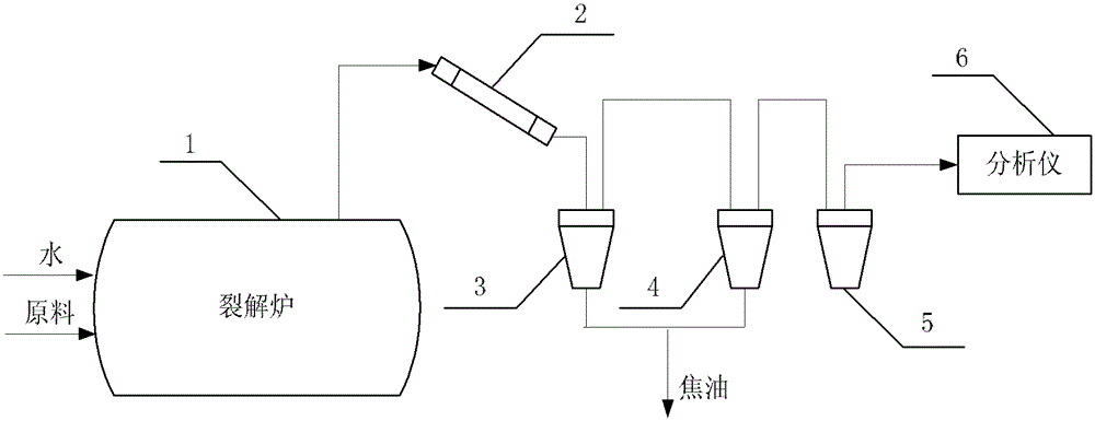
[0024] like Figure 4 As shown, the control system for controlling the reaction temperature of the cracking furnace according to the present invention includes a temperature acquisition module 401 and a two-degree-of-freedom internal model controller 402, wherein: the temperature acquisition module 401 is used to collect the current temperature of the cracking furnace and collect The current temperature obtained is transmitted to the two-degree-of-freedom internal model controller 402; the two-degree-of-freedom internal model controller 402 is used to adjust the heating of the cracking furnace according to the temperature setting value and the current temperature of the cracking furnace The heating power of the device is used to control the temperature ...


PUM


Abstract

The invention aims at defects of large temperature fluctuation and long stabilization time in cracking furnace temperature control in prior arts, and provides a cracking furnace reaction temperature control system and a control method used for overcoming the defects. The cracking furnace reaction temperature control system comprises a temperature collection module and a two-degree-of-freedom internal model controller. The temperature collection module is used for collecting a current temperature of the cracking furnace and for transmitting the collected current temperature to the two-degree-of-freedom internal model controller. The two-degree-of-freedom internal model controller is used for adjusting the heating power of a cracking furnace heating device according to a temperature preset value and the cracking furnace current temperature. The invention also provides a control method used for controlling the cracking furnace reaction temperature. The method comprises the steps that: the cracking furnace current temperature is collected and is transmitted to the two-degree-of-freedom internal model controller; and the two-degree-of-freedom internal model controller adjusts the heating power of a cracking furnace heating device according to a temperature preset value and the cracking furnace current temperature.

Description

technical field [0001] The invention relates to the field of automatic control, in particular to a control system and a control method for controlling the reaction temperature of a cracking furnace. Background technique [0002] In the field of petrochemical industry, petroleum fractionation products are often used as raw materials, and the hydrocarbons with long-chain molecules are broken into various short-chain gaseous hydrocarbons and a small amount of liquid hydrocarbons by using relatively high temperature to provide organic chemical raw materials. figure 1 It is a schematic structural diagram of an existing steam cracking reaction device, which includes a cracking furnace 1, a quencher 2, a first water-cooled separation tank 3, a second water-cooled separation tank 4, an ice-cooled separation tank 5 and an analyzer 6. The furnace 1 in turn comprises a convective section and a radiant section (neither shown). figure 1 The steam cracking process flow of the shown steam...

Claims


Application Information

Patent Timeline
Patent Type & Authority Patents(China)
IPC IPC(8): G05B13/00C10G9/24
Inventor 孙康吴小英李庆吴瑾刘瞻
Owner CHINA PETROLEUM & CHEM CORP
Why Eureka
Try Eureka