Anti-pulling system

An anti-pulling and parallel installation technology, applied in building components, shock-proof and other directions, can solve the problems of endangering the personal safety of buildings, large acceleration and displacement, panic and anxiety, etc., to prolong the service life, ensure safety, and restrain tilt or shaking. Effect

Inactive Publication Date: 2013-05-01
柳州东方工程橡胶制品有限公司
View PDF3 Cites 9 Cited by
  • Summary
  • Abstract
  • Description
  • Claims
  • Application Information

AI Technical Summary

Problems solved by technology

[0002] Due to the development of urban construction, there are more and more high-rise and super high-rise buildings. High-rise and super high-rise buildings are structures with a relatively large aspect ratio. Under the action of strong external forces such as earthquakes, the acceleration and displacement are large, which will cause the building to tilt. When the inclination is large, it will cause the building to overturn, endangering the safety of the building and people; in addition, strong winds will also cause the building to shake, causing people to panic. The higher the building, the more obvious the shaking caused by earthquakes and winds. Key Issues in Earthquake Resistance
[0003] In order to solve the problems of tilting or shaking of high-rise and super-high-rise isolation buildings with relatively large aspect ratios or other engineering structures under the action of earthquake or wind load, the structural design of buildings has always been based on the seismic design method. , this kind of seismic design is committed to ensuring that the structure itself has sufficient strength, stiffness and ductility to achieve the purpose of mitigating earthquake disasters, but the price paid for this design is huge

Method used


Image

  • Anti-pulling system
  • Anti-pulling system
  • Anti-pulling system

Examples


Embodiment 1

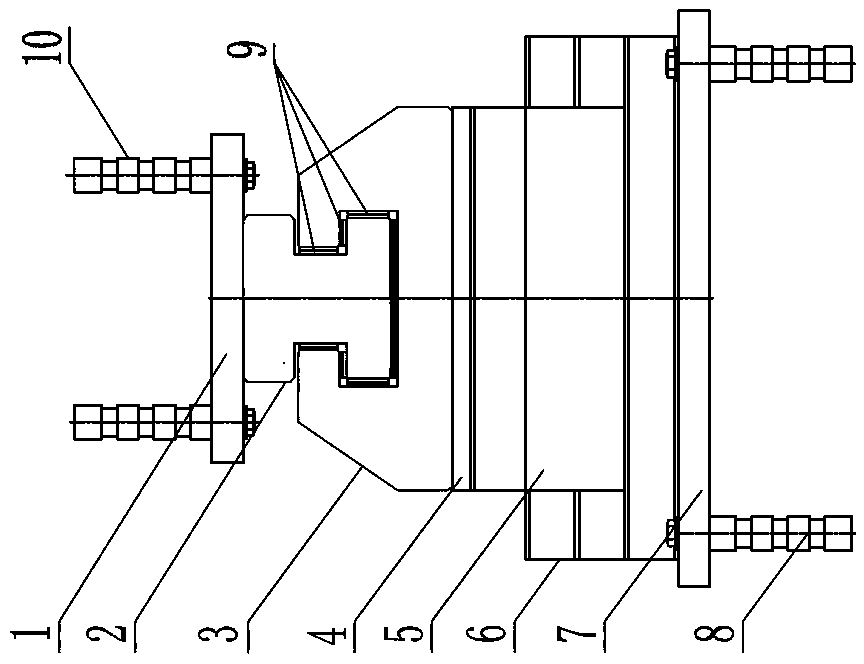
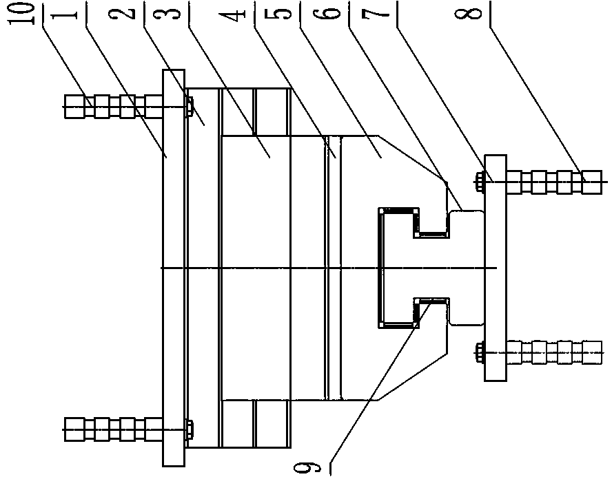
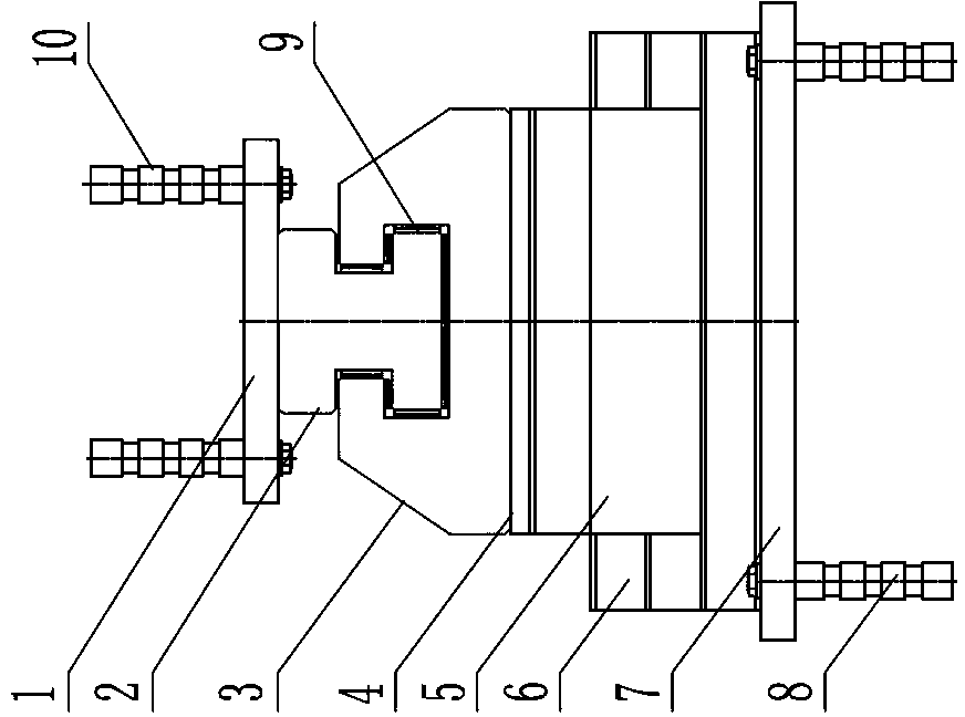
[0035] one A kind of anti-pullout device, comprises upper and lower connecting plate, the upper layer sliding mechanism and the lower layer sliding mechanism that are respectively connected with upper and lower connecting plate, and the middle layer 4 that is connected between the upper layer sliding mechanism and the lower layer sliding mechanism, the upper layer The sliding mechanism has the same structure as the lower sliding mechanism, installed with the back facing, and the sliding directions are perpendicular to each other.

[0036] The upper sliding mechanism includes a set of upper guide rails 2 installed in parallel and an upper slider 3 that is slidably matched with the upper guide rails, and the lower sliding mechanism includes a set of lower guide rails 6 installed in parallel and a lower slider that is slidably matched with the lower guide rails 5. The top surface of the upper guide rail 2 is connected to the upper connection plate 1, the top surface of the lower ...

Embodiment 2

[0040] one A kind of anti-pullout device, its basic structure is identical with embodiment one, comprises upper and lower connecting plate, the upper layer sliding mechanism and the lower layer sliding mechanism that are connected with upper and lower connecting plate respectively, and be connected with the upper layer sliding mechanism and the lower layer sliding mechanism Between the intermediate layer 4, the upper sliding mechanism and the lower sliding mechanism have the same structure, are installed with their backs facing each other, and the sliding directions are perpendicular to each other.

[0041] The difference is that the upper sliding mechanism includes a set of upper guide rails 2 installed in parallel and the upper slider 3 slidingly matched with the upper guide rails, and the lower sliding mechanism includes two sets of lower guide rails 6 installed in parallel and sliding with the lower guide rails. Cooperating with the lower slider 5, the top surface of the u...

Embodiment 3

[0044] one A kind of anti-pullout device, its basic structure is identical with embodiment one, comprises upper and lower connecting plate, the upper layer sliding mechanism and the lower layer sliding mechanism that are connected with upper and lower connecting plate respectively, and be connected with the upper layer sliding mechanism and the lower layer sliding mechanism Between the intermediate layer 4, the upper sliding mechanism and the lower sliding mechanism have the same structure, are installed with their backs facing each other, and the sliding directions are perpendicular to each other.

[0045] The difference is that the upper sliding mechanism includes 2 sets of upper guide rails 2 installed in parallel and the upper slider 3 slidingly matched with the upper guide rails, and the lower sliding mechanism includes 2 sets of lower guide rails 6 installed in parallel and sliding with the lower guide rails. Cooperating with the lower slider 5, the top surface of the up...


PUM


Abstract

An anti-pulling system comprises an upper connecting plate, a lower connecting plate, an upper layer of sliding mechanism, a lower layer of sliding mechanism and intermediate layers, the upper layer of sliding mechanism and the lower layer of sliding mechanism are respectively connected with the upper connecting plate and the lower connecting plate, the intermediate layer is connected between the upper layer of sliding mechanism and the lower layer of sliding mechanism, and the upper layer of sliding mechanism and the lower layer of sliding mechanism have the same structure, are mounted opposite from each other, and can slide in directions perpendicular to each other. The upper (lower) layer of sliding mechanism comprises n sets of upper (lower) guide rails and upper (lower) sliders, the upper (lower) guide rails are mounted in parallel, the upper (lower) sliders are slidably fitted on the upper (lower) guide rails, the top surfaces of the upper guide rails are connected with the upper connecting plate, the top surfaces of the lower guide rails are connected with the lower connecting plate, and the intermediate layers are respectively connected with the bottoms of the upper sliders and the lower sliders. Under the load action of an earthquake or wind, the anti-pulling system can resist the high upward pulling force of a building structure, meanwhile, the anti-pulling system can allow a seismic isolation structure to slide, resist upsetting moment and enhance the anti-leaning or anti-shaking capability of the building structure, and the anti-pulling system can be used along with intermediate seismic isolation rubber bearings and dampers to form a foundation seismic isolation system which can provide the capability of resisting and balancing the horizontal leaning moment of the structure.

Description

technical field [0001] The invention relates to a shock absorbing and isolating device used in high-rise engineering buildings, in particular to an anti-pulling device. Background technique [0002] Due to the development of urban construction, there are more and more high-rise and super high-rise buildings. High-rise and super high-rise buildings are structures with a relatively large aspect ratio. Under the action of strong external forces such as earthquakes, the acceleration and displacement are large, which will cause the building to tilt. When the inclination is large, it will cause the building to overturn, endangering the safety of the building and people; in addition, strong winds will also cause the building to shake, causing people to panic. The higher the building, the more obvious the shaking caused by earthquakes and winds. Key issues of earthquake resistance. [0003] In order to solve the problems of tilting or shaking of high-rise and super high-rise isolat...

Claims


Application Information

Patent Timeline
Patent Type & Authority Applications(China)
IPC IPC(8): E04B1/98
Inventor 何家荣资道铭叶明坤蒙华昌韦胜顺李坤苏兰清韦谋超
Owner 柳州东方工程橡胶制品有限公司
Why Eureka
Try Eureka