Organic light-emitting diode (OLE) pixel driving circuit

A pixel driving circuit and circuit technology, applied in the direction of instruments, static indicators, etc., can solve the problems of affecting the panel layout, the control line cannot be shared, and the IR voltage drop cannot be compensated, so as to improve the plane layout and anti-interference performance, improve the display effect, the effect of improving the display effect

Active Publication Date: 2013-05-01
EVERDISPLAY OPTRONICS (SHANGHAI) CO LTD
View PDF5 Cites 92 Cited by
  • Summary
  • Abstract
  • Description
  • Claims
  • Application Information

AI Technical Summary

Problems solved by technology

However, this circuit cannot compensate for the unevenness of transistor threshold voltage (Vth) and the influence of power supply IR drop (IR drop) on AM-OLED display unevenness
[0005] Aiming at the problem of uneven threshold voltage (Vth) of LTPS transistors, a 4T2C compensation circuit was proposed in the previous technology, which effectively compensated the problem of uneven display caused by the threshold voltage (Vth) of LTPS transistors on AM-OLED. figure 2 is the prior art pixel circuit structure, with image 3 is the prior art timing of driving this circuit
From attached image 3 It can be seen that 3 control lines and 1 data line need to be pulled out, and the pixel circuit needs to consume extra time for Vth compensation during display, and the control lines of adjacent pixel rows cannot be shared, and each row is independently drawn There are many leads, which affects the layout in the panel
This circuit does not compensate for the IR drop and uses a more complex timing

Method used


Image

  • Organic light-emitting diode (OLE) pixel driving circuit
  • Organic light-emitting diode (OLE) pixel driving circuit
  • Organic light-emitting diode (OLE) pixel driving circuit

Examples


Embodiment Construction

[0035] The present invention will be further described below in combination with principle diagrams and specific operation examples.

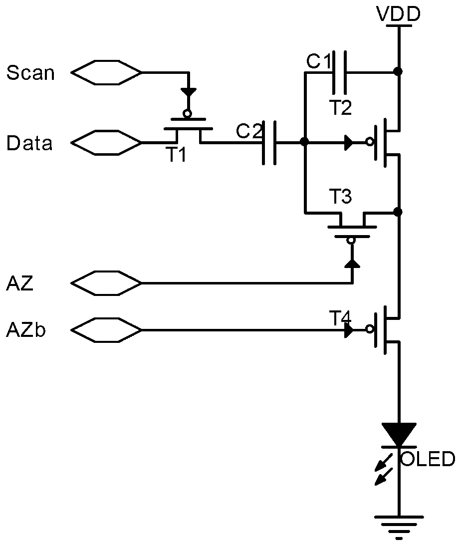
[0036] Such as image 3 As shown, the OLED pixel driving circuit of the present invention includes a circuit part and a driving level part.

[0037] In this specific embodiment, the circuit part includes a first switching transistor T1, a second switching transistor T2, a third switching transistor T3, a fourth switching transistor T4, a driving transistor T5, a first capacitor C1, a second capacitor C2 and an organic light emitting diode diode OLED.

[0038]The gate of the first switching transistor T1 is connected to the current scan line Gn, the first electrode is connected to the data line Dn, the second electrode is connected to the second capacitor C2, the other end of the second capacitor C2 is connected to the gate of the driving transistor T5, and the driving transistor The first electrode of T5 is connected to the first power supply...


PUM


Abstract

The invention discloses an organic light-emitting diode (OLED) pixel driving circuit, comprising a circuit part and a driving time sequence part. The circuit part comprises a first switch transistor, a second switch transistor, a third switch transistor, a fourth switch transistor, a driving transistor, a first capacitor, a second capacitor and an OLED. The driving time sequence part comprises a first scanning line, a second scanning line, a light-emitting control line and a data line. The time sequence of the driving circuit comprises a compensation stage, a data input stage and a display stage. According to the OLED pixel driving circuit disclosed by the invention, the unevenness of a transistor threshold voltage value (Vth) can be compensated, and the influence on the display evenness of an active matrix (AM)-OLED from a power supply IR-drop also can be eliminated, so that the display effect of the AM-OLED is greatly improved, the display effect and the display life of the AM-OLED are increased, meanwhile the pixel circuit driving time sequence is simplified, and the pixel internal plane layout and the anti-interference performance are improved.

Description

technical field [0001] The invention relates to a pixel driving circuit, in particular to an OLED pixel driving circuit applied to LTPS and similar circuits. Background technique [0002] Low temperature polysilicon technology LTPS (Low Temperature Poly-silicon) was originally a technology developed by Japanese and North American technology companies in order to reduce the energy consumption of the Note-PC display and make the Note-PC appear thinner and lighter. It was around the middle of the 1990s. The technology has begun to move towards the trial stage. OLED, a new generation of organic light-emitting liquid crystal panels derived from LTPS, also entered the practical stage in 1998. Its biggest advantages lie in ultra-thin, light weight, low power consumption, and its own light-emitting characteristics, so it can provide more brilliant colors. And clearer images, and more importantly, the production cost is only 1 / 3 of ordinary LCD panels. AM-OLED (Active Matrix / Organi...

Claims


Application Information

Patent Timeline
Patent Type & Authority Applications(China)
IPC IPC(8): G09G3/32
CPCG09G3/3258G09G2300/043G09G2300/0861G09G2320/045
Inventor 秦永亮陈志宏黄初旺
Owner EVERDISPLAY OPTRONICS (SHANGHAI) CO LTD
Why Eureka
Try Eureka