Stator-free brushless dual-rotor outer ring permanent magnet synchronous motor with rotating controller

A synchronous motor, permanent magnet technology, applied in electrical components, electromechanical devices, electric components, etc., can solve the problems of large size, increased probability of wear failure, complex control mechanism, etc., and achieve small size, reduced size, and manufacturing complexity. reduced effect

Inactive Publication Date: 2013-05-01
张建龙 +1
View PDF4 Cites 4 Cited by
  • Summary
  • Abstract
  • Description
  • Claims
  • Application Information

AI Technical Summary

Problems solved by technology

But because it can be regarded as two independent ordinary motors, there must be two controllers, which makes the control mechanism more complicated, and for the motor body, because there is still a stator part in the structure, the volume is relatively large
At the same time, the inverter is fixed outside the motor, and the connection between the output end of the inverter and the input end of the motor basically adopts the connection method of three brushes. The increase in the number of brushes will lead to an increase in the probability of wear and failure.

Method used


Image

  • Stator-free brushless dual-rotor outer ring permanent magnet synchronous motor with rotating controller
  • Stator-free brushless dual-rotor outer ring permanent magnet synchronous motor with rotating controller

Examples


Embodiment 1

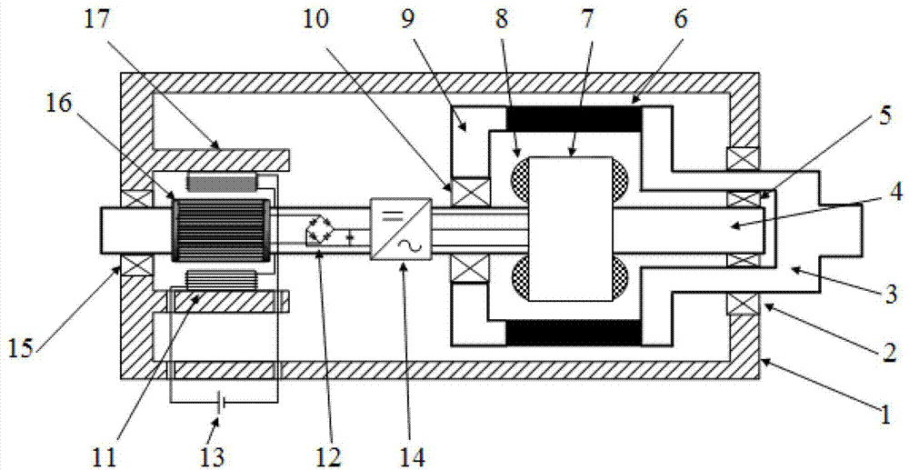
[0030] Such as figure 1 As shown, this embodiment includes: a casing 1, an outer rotor and an inner rotor, the outer rotor includes an outer shaft 3, the inner end of the outer shaft 3 is arranged inside the casing 1, and the inner ends of the outer shaft 3 are staggered along the circumferential direction The permanent magnet 6, the inner end of the outer shaft 3 is provided with an end cover 9, the outer end of the outer shaft 3 protrudes outside the first end of the casing 1; the inner rotor includes an inner shaft 4, and the inner end of the inner shaft 4 is provided with an outer Inside the rotor, an inner rotor core 7 and an inner rotor winding 8 embedded in the inner rotor core 7 are provided on the inner end of the inner shaft 4 corresponding to the permanent magnet 6, and the outer end of the inner shaft 4 is arranged outside the outer rotor. The outer end of the rotating shaft 4 protrudes outside the second end opposite to the first end of the casing; the outer end o...

Embodiment 2

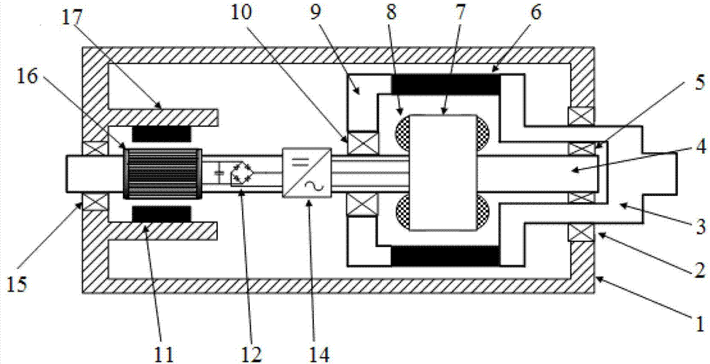
[0048] Embodiment 2 is a modification example of Embodiment 1.

[0049] Such as figure 2 As shown, this embodiment is based on the solution of embodiment 1, and its difference from embodiment 1 is that the inductor structure includes an inductor housing 17 arranged in the second end of the casing and an inductor housing 17 arranged in the inductor housing. The induction permanent magnet 11 and the squirrel-cage aluminum strip structure 16, wherein:

[0050] -The induction permanent magnet 11 is fixed on the inductor housing 17, and the direction of the magnetic field generated is just opposite, and is vertical to the outer end of the inner rotating shaft in space;

[0051] - The squirrel-cage aluminum bar structure 16, whose upper and lower parts have the same direction of the induced magnetic force, is fixed on the outer end of the inner rotating shaft 4 and rotates with the outer end of the inner rotating shaft 4, continuously cutting the induction permanent magnet 11 to g...


PUM


Abstract

The invention discloses a stator-free brushless dual-rotor outer ring permanent magnet synchronous motor with a rotating controller. An outer rotor comprises an outer rotary shaft, the inner end of the outer rotary shaft is arranged in an enclosure, permanent magnets are arranged at the inner end of the outer rotary shaft in a staggered manner along the circumferential direction, an end cover is arranged at the end part of the inner end of the outer rotary shaft, and the outer end of the outer rotary shaft extends out of a first end of the enclosure; an inner rotor comprises an inner rotary shaft, the inner end of the inner rotary shaft is arranged in the outer rotor, an inner rotor core and an inner rotor winding embedded in the inner rotor core are arranged at the inner end of the inner rotary shaft, the outer end of the inner rotary shaft is arranged on the exterior of the outer rotor, and the end part of the outer end of the inner rotary shaft extends out of a second end of the enclosure; and an inverter is arranged at the outer end of the inner rotary shaft in the enclosure, close to the end part of the inner end of the outer rotary shaft, an inductor structure is arranged at the outer end of the inner rotary shaft in the enclosure, close to the second end of the enclosure, and a rectifier is arranged between the inverter and the inductor structure. The stator-free brushless dual-rotor outer ring permanent magnet synchronous motor with the rotating controller is simple in structure, breaks through the limitation of only one rotary shaft, omits the stator part and is applicable to various occasions.

Description

technical field [0001] The invention relates to the technical field of motors, in particular to a statorless brushless double rotor outer ring permanent magnet synchronous motor which is rotated by a controller. Background technique [0002] The dual-rotor motor has two rotors and rotating shafts with independent rotational speeds, which can realize dual-axis independent drive, so it has broad application prospects in various occasions, such as the electric drive system of hybrid vehicles, the electric stepless motor of automobiles and wind turbines Transmission and modern machine tool CNC turntable, etc. [0003] At present, the double-rotor permanent magnet motor that has been published at home and abroad is a new type of motor that is set together with an outer rotor permanent magnet motor and an inner rotor permanent magnet motor and shares a stator. But because it can be regarded as two independent ordinary motors, there must be two controllers, which makes the control...

Claims


Application Information

Patent Timeline
Patent Type & Authority Applications(China)
IPC IPC(8): H02K16/02H02K11/00H02K11/049H02K11/20
Inventor 殷承良张希沈辉
Owner 张建龙
Why Eureka
Try Eureka